GitHub
Get the tutorial project from GitHub - It contains all the assets necessary to achieve the final result!
This tutorial teaches you how to use compute shaders and shader variants to create fast, great-looking gameplay data visualizations. At the same time, you’ll get a basic understanding of deferred rendering and how to write shaders that support it!
This case study is aimed towards intermediates. While it should be easy for beginners to follow the step-by-step instructions, I highly recommend you start with a more beginner friendly tutorial like the Overwatch Shield Case Study in order for you to be able to understand everything in detail.
There are some similarities to the Civilization Fog of War Case Study (mainly the mask rendering setup), however I tried to add a couple of new techniques like the deferred shading support and shader variants to make sure it’s still interesting for those of you who did the other tutorial.
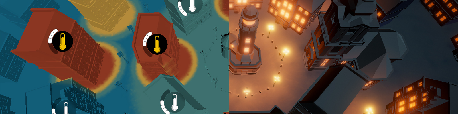
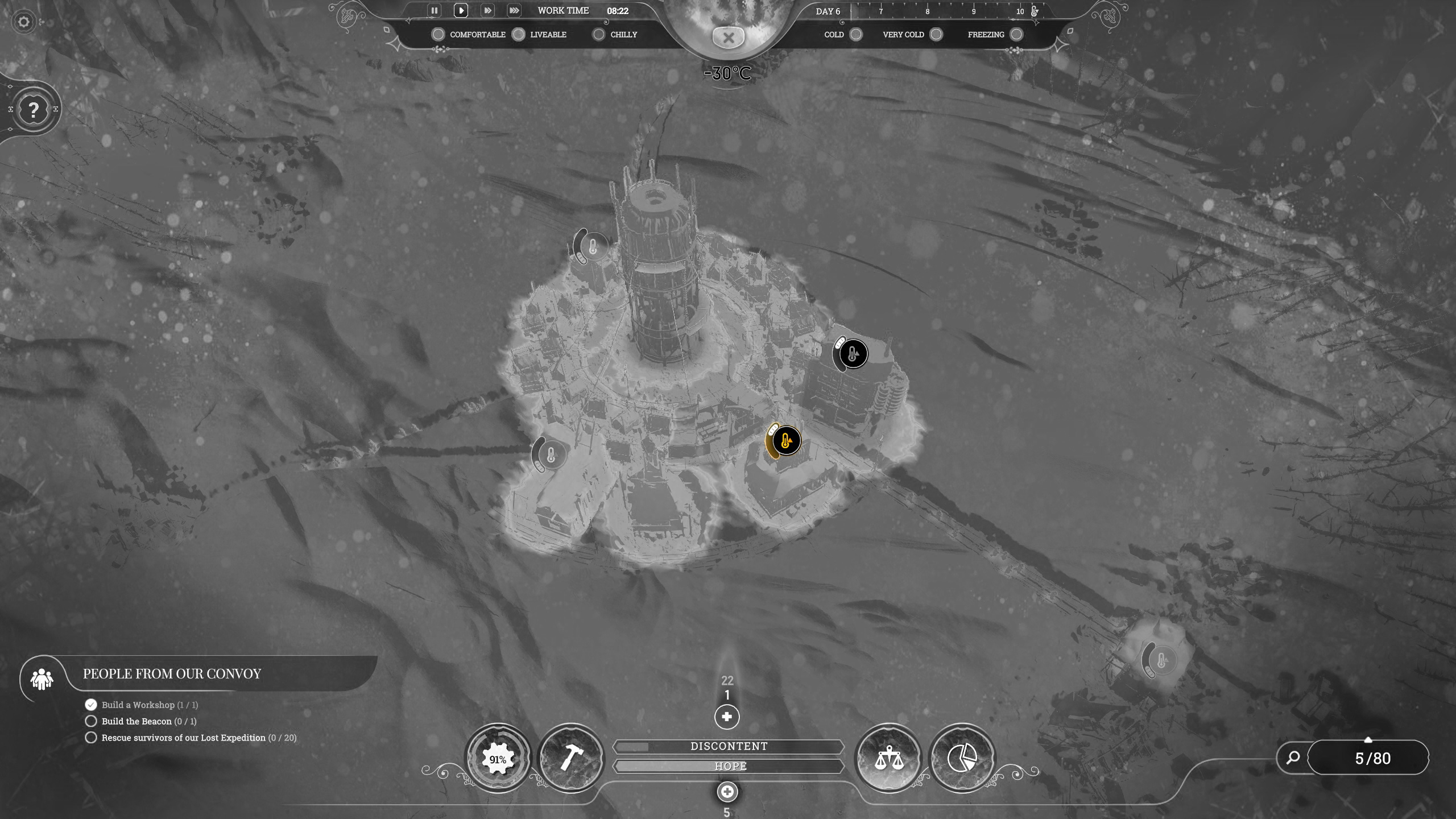
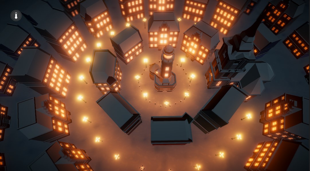
We start by doing the same thing as always: Playing the game and looking at the effect we want to recreate. For convenience and in case you don’t own the game yourself I took a screenshot of the effect and highlighted the interesting areas.
The heatmap view in Frostpunk is essentially a data visualization that shows you which temperature level each building has. A chilly or lower temperature means that the inhabitants of the building are at risk of freezing or even dying. Therefore, you want to maintain a medium to high temperature in each building. The heatmap helps you to get a quick overview of the current situation. At the centre of the settlement is the generator, the main source of the heat produced in the city. Let’s examine it a bit closer to get a better idea of how this effect was achieved.

At first glance, it might look as if the colouring of the building is quite complex and creating a solution for different kinds of buildings is difficult. However, if you look more closely at the transition between red and orange areas, you might notice that the position of this transition doesn’t change along the height of the building. In other words: The y coordinate of the position on the model doesn’t matter, only the x and z coordinates do. I marked the point of transition across different heights in the next image, it should clarify what I mean.
The temperature does only change based on the distance to the building's centre. That makes things way easier for us. Instead of having to find a 3-dimensional solution, we can simply calculate the temperature for every point in the world in 2D and display it on the object at the respective x/z coordinate. If this approach sounds somewhat familiar to you, it might be because we did something comparable to create the fog of war effect in the Civilization Fog of War Case Study.
The highlighted building clearly shows another part of the effect. The transition between different colours is not a perfect circle, but rather there is some form of noise added to the temperature value to make it appear more random.

If we add the next temperature level to the visualization this becomes even more visible. The noise pattern to me looks like a simple perlin noise, which is what we’ll be using in this project.
Alright so one more little detail I wanted to add is the heater UI. Heaters in Frostpunk can be used to boost the temperature in individual buildings and it allows us to control the demo. The Heater UI has this unique, curved slider and the colour of background and icon changes upon activation. I created some sprites in Affinity Designer to achieve this effect and a little C# script to control it. More about that in the next chapter. One thing I want to highlight here is the background blur present. I used the shader we created in the UI Blur Tutorial and added it to the project to achieve this effect. You should check it out if you want to know how to create such a blur shader yourself.
With all of this out of the way, let’s take a look at the Unity project for this tutorial.
As usual, I prepared a template project for you so we can focus on what’s important rather than having to write e.g. code for UI handling. I’ll quickly go through the project’s setup in order to bring you up to speed.
Template ProjectFirst of all, I want to start with the assets. All of the nice 3D models in this project are part of the Low Poly Brick Houses asset store package. While the asset itself is already free, the author even allowed me to include the assets in the GitHub projects for convenience. He is offering a lot of other free asset packs as well, so you really should head to his asset store page and take a look around.
Second, there is a snow texture in the project which is used on the ground. The texture is available for free on cc0textures, they have a lot of really good ones available under the creative commons license over there. Usually they come with a variety of PBR maps which would make the snow look way cooler. Nonetheless, PBR is unfortunately way out of the scope of this tutorial so we have to work with only the colour map.
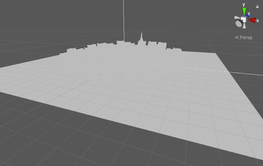
The first thing you’ll notice when opening the tutorial scene found in “Scenes/TutorialScene” is that it’s currently quite ugly and just a grey blob. However, it already contains everything necessary to achieve the visuals of the final project. If you enter play mode, you should see the snow particles and you should be able to toggle the temperature UI using the button in the top left corner. If you are experiencing low framerates, it is most likely due to the snow particles, as they are using Unity’s CPU based particle system. You can simply disable the “SnowVFX” object in the scene hierarchy to fix this.
Speaking of the hierarchy, let’s take a closer look at the structure of the project in order for you to fully understand what’s going on. “-----Objects” contains all the 3D models in the scene, i.e. the ground, the buildings and the lamps. All the UI elements, as well as the event system, are located in the “-----UI” object. The UI elements are using the background blur shader introduced in a previous basics tutorial.
If you are interested in how to create a UI background blur, check out the basics tutorial here.
There are two lights in the scene, the “Moon” and the “HeatViewLight”. Both are located in “-----Lights”, and both are directional lights. “Moon” is active when the heatmap is disabled, “HeatViewLight” is active when the heatmap is enabled. We want to be able to see the shapes of the buildings when the heatmap is active, we therefore need an active light for it as well. It has to be way brighter than the regular one though and rather than changing the settings of the existing light we might as well create a new one and toggle them.
Let’s look at the camera next.
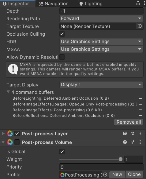
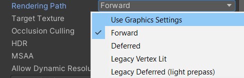
There are two things worth noting here: First, the rendering path is currently set to forward. As mentioned before, we’ll be using the deferred pipeline for rendering, so we have to change that. Rather than setting it to “Deferred”, we’ll be setting it to “Use Graphics Settings”.
Instead of having to set the rendering path for every camera, we can now simply set it up using the graphics project settings.
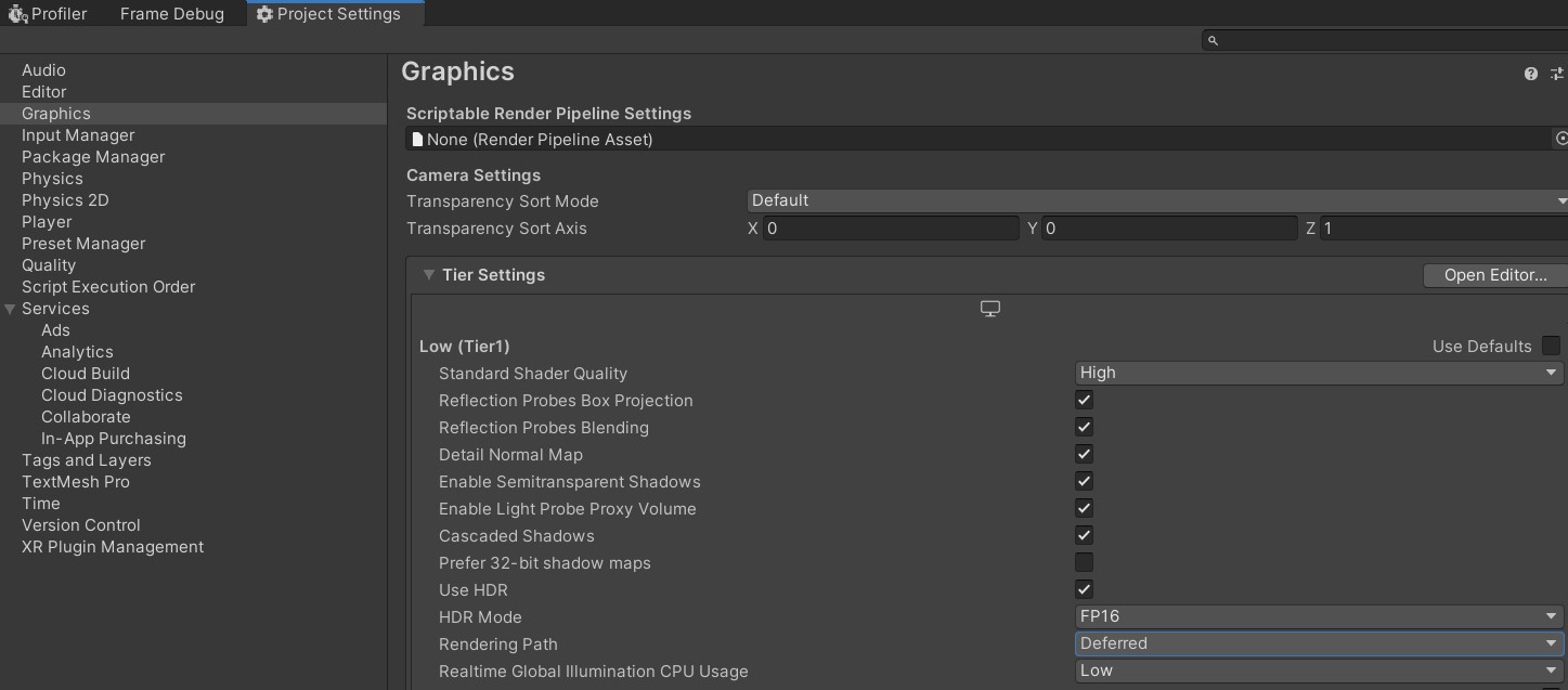
I already set the rendering path to deferred for every PC tier, if you are using another platform you have to make sure to set it to the deferred renderer as well!
The tiers in the graphics project settings allow you to adapt the render settings to a variety of hardware tiers. You could e.g. use a deferred pipeline for high-end systems while using a forward renderer for low-end systems. In practice the overhead is usually not worth the additional effort during development and a single, scalable pipeline is the better option.
The second thing worth noting on the camera is that I have the post-processing stack set up for later use. Currently there’s no effect there, we’ll be adding some later in the tutorial.
Lastly, let’s take a quick look at the two controller scripts in “-----Controller”. The “HeatViewController” is managing the transition between the regular view and our heatmap view. When switching to the heatmap, it deactivates the moon directional light and enables the heatmap directional light, it deactivates the post processing, it deactivates all the lamppost lights in the scene, it enables the UI elements, and it disables the snow particles. Furthermore, it enables the material keyboard “RENDER_HEAT”. We’ll talk about this in a later chapter (there’s way too much foreshadowing in this tutorial…). When transitioning to the regular view, the script does the opposite of all of those steps.
The other script here is the “MaskRenderer”. As the name suggests, it is responsible for rendering the mask for our heatmap, i.e. the texture with the colour-coded temperature values.
As discussed in the effect analysis section, we only need this 2-dimensional texture to colour our 3D world, since we can ignore the y position when shading the objects.
In order to fully understand this tutorial, it is extremely important to understand how the mask rendering script works. We’ll go through it step-by-step, if you have done the Civilization Fog of War tutorial, lots of this should be familiar to you.
private static List<buildings>;

public static void RegisterBuilding(Building building)
{
    buildings.Add(building);
}
The script keeps track of all the buildings in the scene in this list. To do that, each building has a script that calls the “RegisterBuilding” function during start-up. The building script contains the building’s temperature and radius, and it animates the temperature transition when the UI button is used.
[SerializeField]
private ComputeShader computeShader = null;

[Range(64, 4096)]
[SerializeField]
private int TextureSize = 2048;

[SerializeField]
private float MapSize = 0;
The compute shader property holds the actual shader file containing the function we are using for the rendering of the heatmap. In our case that is “MaskCompute.compute”. There is also a variable that let’s us control the size this texture should have (2048 by default which looks good enough for our purposes) and a variable containing the size of the 3D scene. We need this size to map our texture’s uv coordinates (which are [0;1]) to the area in the world we want our heatmap to be displayed on.
[SerializeField]
private float BlendDistance = 4.0f;

public Color MaskColor0;
public Color MaskColor1;
public Color MaskColor2;
public Color MaskColor3;
I mentioned before, that if you take a closer look at the transition between two different colours, e.g. red and blue, you’ll notice that the colours don’t change directly from one to another. Instead, they are blending between the two of them over some distance by using the yellow tint in between. The “BlendDistance” parameter lets us control this distance. The four colour variables are to adjust the different colour tones of the heatmap (as you have probably guessed).
public Texture2D NoiseTexture;

[Range(0.0f, 5.0f)]
public float NoiseDetail = 4.0f;
The noise texture is used to make the blend between the colours less uniform and instead have this random pattern between them. The detail value allows us to adjust the resolution of the noise by simply multiplying it to the UV coordinates during sampling. This works similar to the tiling value you can set in a material for every texture in Unity.
private RenderTexture maskTexture;The “maskTexture” is the texture this whole script is all about, the one we are writing the actual heatmap to. You’ll see how it’s binded to the different shaders later in this chapter.
private static readonly int textureSizeId = Shader.PropertyToID("_TextureSize");
private static readonly int buildingCountId = Shader.PropertyToID("_BuildingCount");
private static readonly int mapSizeId = Shader.PropertyToID("_MapSize");
private static readonly int blendId = Shader.PropertyToID("_Blend");

private static readonly int color0Id = Shader.PropertyToID("_Color0");
private static readonly int color1Id = Shader.PropertyToID("_Color1");
private static readonly int color2Id = Shader.PropertyToID("_Color2");
private static readonly int color3Id = Shader.PropertyToID("_Color3");

private static readonly int noiseTexId = Shader.PropertyToID("_NoiseTex");
private static readonly int noiseDetailId = Shader.PropertyToID("_NoiseDetail");

private static readonly int maskTextureId = Shader.PropertyToID("_Mask");

private static readonly int buildingBufferId = Shader.PropertyToID("_BuildingBuffer");
Okay so let’s talk about this block of code here. Inside Unity’s backend, every shader variable has a specific ID. If we want to access the variable (e.g. to bind the mask texture to it), we need this ID. To avoid having to look up the ID every time we access any of those variables in our shaders, we cache them here once. We could call all those functions with the name instead of the ID; however, Unity would have to look up the ID internally. Caching them here is simply a performance improvement and a good practice you should get used to.
private struct BuildingBufferElement
{
    public float PositionX;
    public float PositionY;
    public float Range;
    public float Heat;
}

private List<BuildingBufferElement> bufferElements;
private ComputeBuffer buffer = null;
In addition to the output texture and the variables there is one more thing we need in our compute shader and that is the building information. We need a buffer we can fill with the current information every frame and which we can provide to the compute shader. A compute buffer is just what we need. Once we use it later in the script, you’ll see how easy it is to work with such a buffer.
private void Awake()
{
    buildings = new List<Building>();

#if UNITY_EDITOR_OSX || UNITY_STANDALONE_OSX
    maskTexture = new RenderTexture(TextureSize, TextureSize, 0, RenderTextureFormat.ARGB32, RenderTextureReadWrite.Linear)
#else
    maskTexture = new RenderTexture(TextureSize, TextureSize, 0, RenderTextureFormat.ARGB32)
#endif
    {
        enableRandomWrite = true
    };
    maskTexture.Create();

    computeShader.SetInt(textureSizeId, TextureSize);
    computeShader.SetTexture(0, maskTextureId, maskTexture);

    computeShader.SetFloat(blendId, BlendDistance);

    computeShader.SetVector(color0Id, MaskColor0);
    computeShader.SetVector(color1Id, MaskColor1);
    computeShader.SetVector(color2Id, MaskColor2);
    computeShader.SetVector(color3Id, MaskColor3);

    computeShader.SetTexture(0, noiseTexId, NoiseTexture);
    computeShader.SetFloat(noiseDetailId, NoiseDetail);

    Shader.SetGlobalTexture(maskTextureId, maskTexture);
    Shader.SetGlobalFloat(mapSizeId, MapSize);

    bufferElements = new List<BuildingBufferElement>();
}
The Awake() function handles the setup of all of our variables. It starts by initialising the building list so the building scripts can register themselves. Since the building script’s logic runs in Start() (which is called after Awake()), it is assured that the list is ready when needed.
A temporary render texture with the set texture size is created afterwards. In order to be able to write to the texture in our compute shader, “enableRandomWrite” has to be set to true.
Once it is created, we can bind the texture to the shader variable. We are also setting the values for all the other shader variables we need, such as the texture size, the colours, the noise texture and the noise tiling. That’s everything we need to render the mask texture in our compute shader.
What’s left is that we bind the texture to our vertex/fragment shaders so we can use it there. For this tutorial we do this by simply setting it as global shader variable, which means we can use it in every shader where we have a sampler2D with its names. This works fine for a tutorial; however, you shouldn’t use this to set a lot of shader variables in a large-scale project as it can negatively impact performance.
Lastly, we create a list for the compute buffer elements which we’ll use to fill the compute buffer later.
private void OnDestroy()
{
    buffer?.Dispose();

    if (maskTexture != null)
    DestroyImmediate(maskTexture);
}
Compute buffers and render textures allocate memory when created. Since we are all super clean coders (*cough*) we should clean up after ourselves and make sure we destroy those objects when closing our game.
private void Update()
{
    bufferElements.Clear();
    foreach (Building building in buildings)
    {
        BuildingBufferElement element = new BuildingBufferElement
        {
            PositionX = building.transform.position.x,
            PositionY = building.transform.position.z,
            Range = building.Range,
            Heat = building.Heat
        };
        bufferElements.Add(element);
    }

    buffer?.Release();
    buffer = new ComputeBuffer(bufferElements.Count * 4, sizeof(float));

    buffer.SetData(bufferElements);
    computeShader.SetBuffer(0, buildingBufferId, buffer);

    computeShader.SetInt(buildingCountId, bufferElements.Count);

    computeShader.Dispatch(0, Mathf.CeilToInt(TextureSize / 8.0f), Mathf.CeilToInt(TextureSize / 8.0f), 1);
}
Alright, so let’s talk about what’s happening every frame in Update(). We start by recreating our compute buffer with the current building information (the temperatures might have changed). We release last frame’s compute buffer and create a new one. When creating a compute buffer, we have to provide the number of elements and the size of each element (in bytes) to the buffer so the rendering backend can reserve the appropriate amount of GPU memory. In our case we have 4 elements per buffer (thus bufferElements.Count * 4 elements total) and each element is the size of a float. The sizeof operator gives us this value.
Now that we have an empty buffer with the right size, we have to fill it. This is simply done by calling SetData() on it and giving it the list with the previously updated building structs.
Just as we did for the other variables, we have to bind the buffer to our compute shader.
I’m trying to keep this compute shader as simple as possible, so for this tutorial we are providing the number of elements in our structured buffer as a separate variable. I’ll probably make a more complex compute tutorial in the future where I’ll go into more depth on some of the possibilities.
The last thing we have to do in our Update() function is to run the actual compute shader. Compute shaders run in thread groups of specified dimensions. If you take a look at the “MaskCompute.compute” shader located in “Assets/Shaders”, you’ll notice the following line:
[numthreads(8,8,1)]This tells the compiler that we want to run this compute shader in 8x8x1 threads simultaneously. This is called a thread group. Since we are using our compute shader to render to a texture, you can intuitively think of this as us running the compute shader on 8x8 pixels of the render texture at once. Obviously, our render texture is larger than 8x8 pixels. Therefore, we have to run the compute shader multiple times, how many times exactly depends on how many 8x8 patches we need to render the whole texture. For example, if we have a 512x512 render texture we need to run our compute shader 64x64 times to render the whole thing. Those are the thread group size parameters we are providing in the Dispatch() call at the end of the Update() function.
The first parameter of the function, which is set to 0, is the ID of the compute kernel we want to use. A compute shader file can have multiple kernels (think of them as main functions of a program) and we need to specify which one we want to use. In our case there’s only one kernel and thus the ID is 0.
And with that we are done with the setup of the template project! Quite a lot of code is required to control the effect but with it out of the way we can focus on the exciting part in this tutorial: the shaders!
Every lamppost in the scene has a point light on it that illuminates the environment. There are 29 point lights total in the scene. If you have worked with a lot of lights in a scene before, you probably have had performance issues on lower-end devices because of it. This happens due to the way forward rendering works. In forward rendering, each object is rendered once per light and the results are blended with each other. Basically, what this means is that the whole scene needs to be rendered one more time each frame for each light you are adding to it. The performance hit can be reduced by checking which object is in range of which light before rendering them but even then, the performance hit is pretty massive. Lighting calculations are typically the most expensive part of a shader, especially when there's complex, physically-based lighting.
So how can we support more light sources? There are two possibilities here: Baking the lights and deferred rendering. Baked lighting is really fast during runtime as it is just a lookup of the baked value instead of the full lighting calculations, however the lights cannot change at all. If we want to have dynamic lights this is not an option. Deferred rendering is a middle ground and allows us to have a large amount of lights while still maintaining a good overall performance.
The basics of deferred rendering are actually quite simple. Instead of rendering each object for each light we render each object once and store the values we need for the lighting calculations (e.g. normal, emission, …) in a series of buffers. Once we rendered all objects in the scene into these buffers, we then do lighting calculations for every pixel on screen. With forward rendering it can happen that we calculate lighting for an individual pixel tens or hundreds of times depending on how many light sources there are. Deferred rendering only runs the lighting calculations once for every pixel and thus allows us to support way more lights than forward rendering. These series of buffers are typically referred to as “G-Buffer”.
I barely scratched the surface of deferred rendering here. You should check out a more detailed explanation of the topic if you are interested, like the one on tutsplus.
If we want to create a shader in Unity that works with the internal deferred renderer, all we have to do is fill the G-Buffer and let Unity take care of the rest. Internally, Unity performs lighting calculations using their standard PBR lighting model for us. It is possible to override the shader used for deferred lighting calculations; however, this is out of the scope for this tutorial. For now, the standard lighting will do just fine.
Let’s write a simple deferred shader for the objects in our scene. We want it to support a main colour texture, emission and we want it to display some snow on top of objects.
Open the “BuildingShader” in “Assets/Shaders” and take a quick look at it. Thus far, it is a pretty barebone forward shader like you have probably seen before. All it does is convert the vertex position from object to clip space and output the grey colour we saw all over the scene.
We start by adding a bunch of properties we need for shader. “_MainTex” is our colour texture, and there’s nothing really special about it. The “_Emission” colour is used to make our lampposts and windows glow. In combination with the bloom post-processing effect we are adding later, this adds a lot of atmosphere to the final project. Make sure the variable names are identical to mine if you want the variables to automatically assign the values I am using in the final version of the project. Since we are working with emission, we need the HDR colour picker in Unity to support intensity. To tell Unity this, we have to mark our variable with the “[HDR]” drawer. Finally, we add a colour variable for the snow, as well as an angle variable which we can use to set the angle at which snow should be displayed on the object.
Properties
{
+   _MainTex("Texture", 2D) = "white" {}
+   [HDR]_Emission("Emission", Color) = (0.0, 0.0, 0.0, 0.0)
+   _SnowColor("Snow Color", Color) = (1.0, 1.0, 1.0, 1.0)
+   _SnowAngle("SnowAngle", float) = 0.0
}
As usual, we have to add variables to our HLSL code for each of the properties. For the texture, we also declare the “_ST” variable to support tilling and offset of the texture.
+   sampler2D _MainTex;
+   float4 _MainTex_ST;

+   float4 _Emission;

+   float4 _SnowColor;
+   float _SnowAngle;
We have to tell the renderer that this shader is used for deferred rendering rather than the default forward rendering. We do this by setting the “LightMode” tag to “Deferred”.
+ Tags {"LightMode" = "Deferred"}Since we aren’t writing to the G-Buffer yet, the objects that use this shader will disappear from the scene. Let’s adapt our appdata and v2f structs next.
struct appdata
{
    float4 vertex : POSITION;
+   float3 normal : NORMAL;
+   float2 uv : TEXCOORD0;
};
Appdata contains the vertex attributes we need for rendering. The object space position is already in there; we also need the object space normal for lighting calculations and the uv coordinates for texturing.
struct v2f
{
    float4 vertex : SV_POSITION;
+   float3 normal : NORMAL;
+   float2 uv : TEXCOORD0;
};
The v2f struct already contains a variable for the vertex position in clip space. We have to add one for the world space normal and for the uv coordinates.
Let’s create a struct for the G-Buffer so we can fill it in our fragment shader. We have to make sure the format of this buffer matches the one Unity expects to get from us. Unity’s G-Buffer format contains 4 textures. The first one is for the albedo colour, the second one for the specular colour, the third one is for the world space normal and the last one for emission.
+   struct gbuffer
+   {
+      float4 albedo : SV_Target0;
+      float4 specular : SV_Target1;
+      float4 normal : SV_Target2;
+      float4 emission : SV_Target3;
+   };
A forward shader in Unity writes the result of the fragment shader to SV_TARGET. For the G-Buffer, we are writing to SV_Target0, SV_Target1, SV_Target2 and SV_Target3. Those are the 4 textures in our G-Buffer. Since we aren’t writing to SV_TARGET anymore, we have to remove it from the fragment function. We are also returning a gbuffer struct instead of the single float4 colour now.
+   gbuffer frag(v2f i)
+   {
+       gbuffer o;

+       return o;
-       return float4(0.5f, 0.5f, 0.5f, 1);
+   }
Next up is the vertex shader. We are already transforming the vertex position in it to clip space and writing it into our v2f struct. For the normal, we can use the built-in “UnityObjectToWorldNormal()” function to transform it from object to world space. For the uv coordinates, we can use the built-in “TRANSFORM_TEX” macro to adjust the uv for tilling and offset.
v2f vert (appdata v)
{
    v2f o;
    o.vertex = UnityObjectToClipPos(v.vertex);
+   o.normal = UnityObjectToWorldNormal(v.normal);
+   o.uv = TRANSFORM_TEX(v.uv, _MainTex);
    return o;
}
All that’s left is to fill the G-Buffer in the fragment function. Let’s start with the albedo buffer. What we want to achieve here is that there is snow on the roof of a building but not on the sides of it. To do this we have to check whether the normal of the object at the position we are shading is pointing somewhat upwards or not. The easiest way to achieve this is to calculate the dot product of our normal and the up vector (0, 1, 0). The dot product returns 1 if the angles are identical, -1 if they are pointing into the exact opposite direction and 0 if they are orthogonal to each other.
gbuffer frag(v2f i)
{
+   i.normal = normalize(i.normal);

    gbuffer o;

+   float normalDot = dot(i.normal, float3(0.0f, 1.0f, 0.0f));

    return o;
}
We can now tell our shader to draw the snow colour instead of the colour texture if the dot product is larger than the value we set for the “_SnowAngle” variable. This allows us to adjust the angle of the surface compared to the up vector for which there should be snow. Don’t forget to normalize the normal vector in the fragment shader, as it might no longer be normalized after the rasterization stage!
Due to the way the rasterizer interpolates the values inside the v2f struct, it is possible that the normal vector is no longer normalized. This tutorial entry on lighthouse3d explains it really well.
gbuffer frag(v2f i)
{
    i.normal = normalize(i.normal);

    gbuffer o;

    float normalDot = dot(i.normal, float3(0.0f, 1.0f, 0.0f));
+   if (normalDot < _SnowAngle)
+       o.albedo = tex2D(_MainTex, i.uv);
+   else
+       o.albedo = _SnowColor;

    return o;
}
Next up is the specular colour. I decided to not draw a specular highlight and therefore we can simply set this colour to black (0,0,0).
gbuffer frag(v2f i)
{
    i.normal = normalize(i.normal);

    gbuffer o;

    float normalDot = dot(i.normal, float3(0.0f, 1.0f, 0.0f));
    if (normalDot < _SnowAngle)
        o.albedo = tex2D(_MainTex, i.uv);
    else
        o.albedo = _SnowColor;
+   o.specular = float4(0.0f, 0.0f, 0.0f, 0.0f);

    return o;
}
The normal is also pretty straight forward. We already calculated it in the vertex shader and only have to write it to the G-Buffer. There is only a slight issue here: our normal vector’s values range from [-1;1] while our G-Buffer is a regular texture that stores values from [0;1]. We therefore have to remap the range of the values before writing the normal to the G-Buffer.
gbuffer frag(v2f i)
{
    i.normal = normalize(i.normal);

    gbuffer o;

    float normalDot = dot(i.normal, float3(0.0f, 1.0f, 0.0f));
    if (normalDot < _SnowAngle)
        o.albedo = tex2D(_MainTex, i.uv);
    else
        o.albedo = _SnowColor;
    o.specular = float4(0.0f, 0.0f, 0.0f, 0.0f);
+   o.normal = float4(i.normal * 0.5f + 0.5f, 0.0f);

    return o;
}
The emission however is really straightforward. We simply assign the colour value from our variable and we’re done.
gbuffer frag(v2f i)
{
i.normal = normalize(i.normal);
gbuffer o;
float normalDot = dot(i.normal, float3(0.0f, 1.0f, 0.0f));
if (normalDot < _SnowAngle)
o.albedo = tex2D(_MainTex, i.uv);
else
o.albedo = _SnowColor;
o.specular = float4(0.0f, 0.0f, 0.0f, 0.0f);
o.normal = float4(i.normal * 0.5f + 0.5f, 0.0f);
+ o.emission = _Emission;
return o;
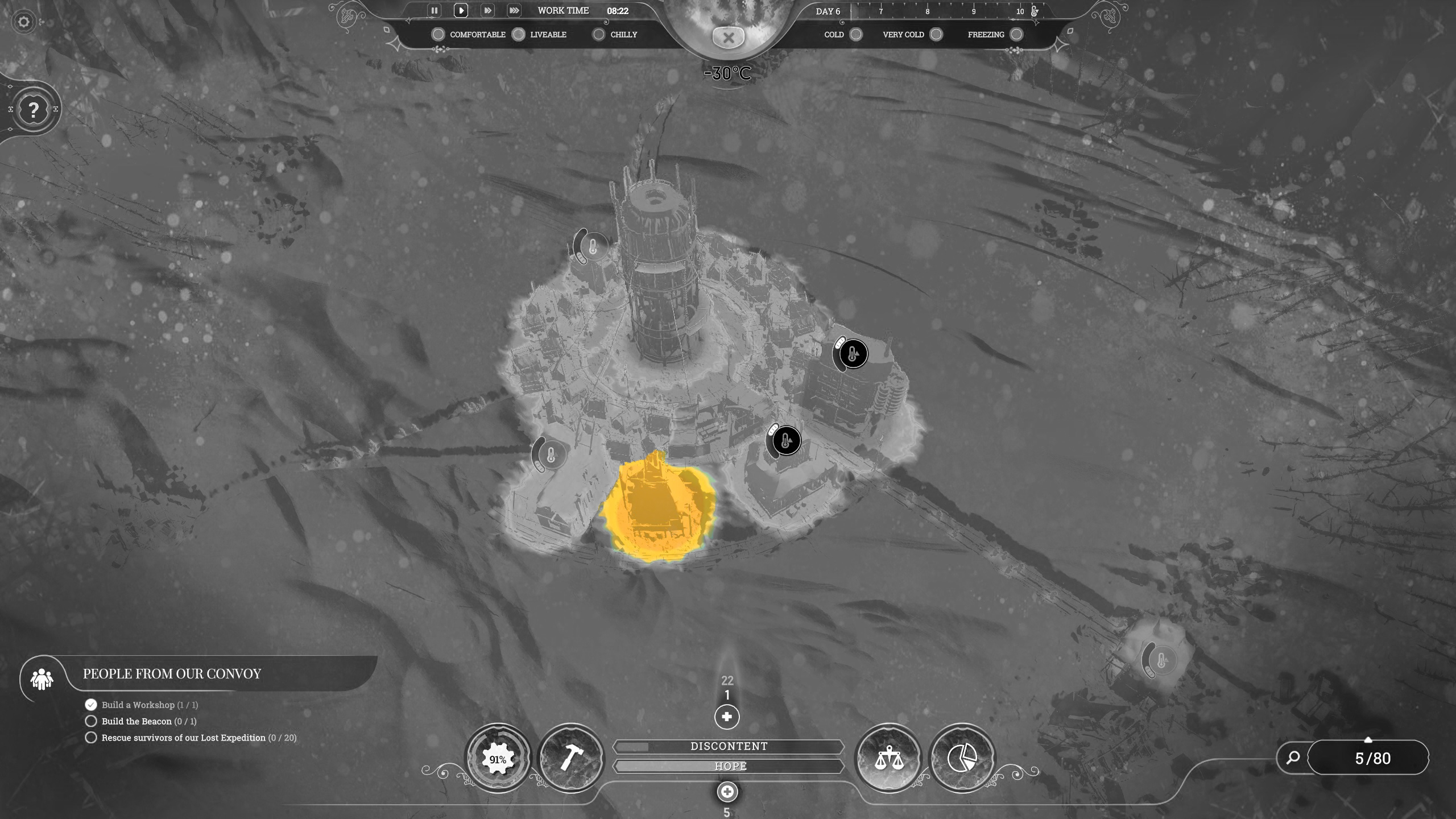
}And with that you should see the following result:
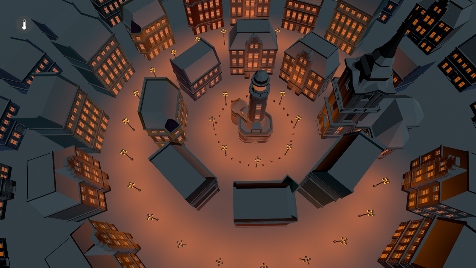
That’s the regular view all done! In the next to chapters we’ll render the heatmap texture in the compute shader and adapt this shader to be able to sample it and switch between the two views.
Here is how the shader should look like after this chapter:
Shader "Lexdev/CaseStudies/FrostpunkHeatmap"
{
Properties
{
_MainTex("Texture", 2D) = "white" {}
[HDR]_Emission("Emission", Color) = (0.0, 0.0, 0.0, 0.0)
_SnowColor("Snow Color", Color) = (1.0, 1.0, 1.0, 1.0)
_SnowAngle("SnowAngle", float) = 0.0
}
SubShader
{
Pass
{
Tags {"LightMode" = "Deferred"}
HLSLPROGRAM
#pragma vertex vert
#pragma fragment frag
#include "UnityCG.cginc"
struct appdata
{
float4 vertex : POSITION;
float3 normal : NORMAL;
float2 uv : TEXCOORD0;
};
struct v2f
{
float4 vertex : SV_POSITION;
float3 normal : NORMAL;
float2 uv : TEXCOORD0;
};
struct gbuffer
{
float4 albedo : SV_Target0;
float4 specular : SV_Target1;
float4 normal : SV_Target2;
float4 emission : SV_Target3;
};
sampler2D _MainTex;
float4 _MainTex_ST;
float4 _Emission;
float4 _SnowColor;
float _SnowAngle;
v2f vert (appdata v)
{
v2f o;
o.vertex = UnityObjectToClipPos(v.vertex);
o.normal = UnityObjectToWorldNormal(v.normal);
o.uv = TRANSFORM_TEX(v.uv, _MainTex);
return o;
}
gbuffer frag(v2f i)
{
i.normal = normalize(i.normal);
gbuffer o;
float normalDot = dot(i.normal, float3(0.0f, 1.0f, 0.0f));
if (normalDot < _SnowAngle)
o.albedo = tex2D(_MainTex, i.uv);
else
o.albedo = _SnowColor;
o.specular = float4(0.0f, 0.0f, 0.0f, 0.0f);
o.normal = float4(i.normal * 0.5f + 0.5f, 0.0f);
o.emission = _Emission;
return o;
}
ENDHLSL
}
}
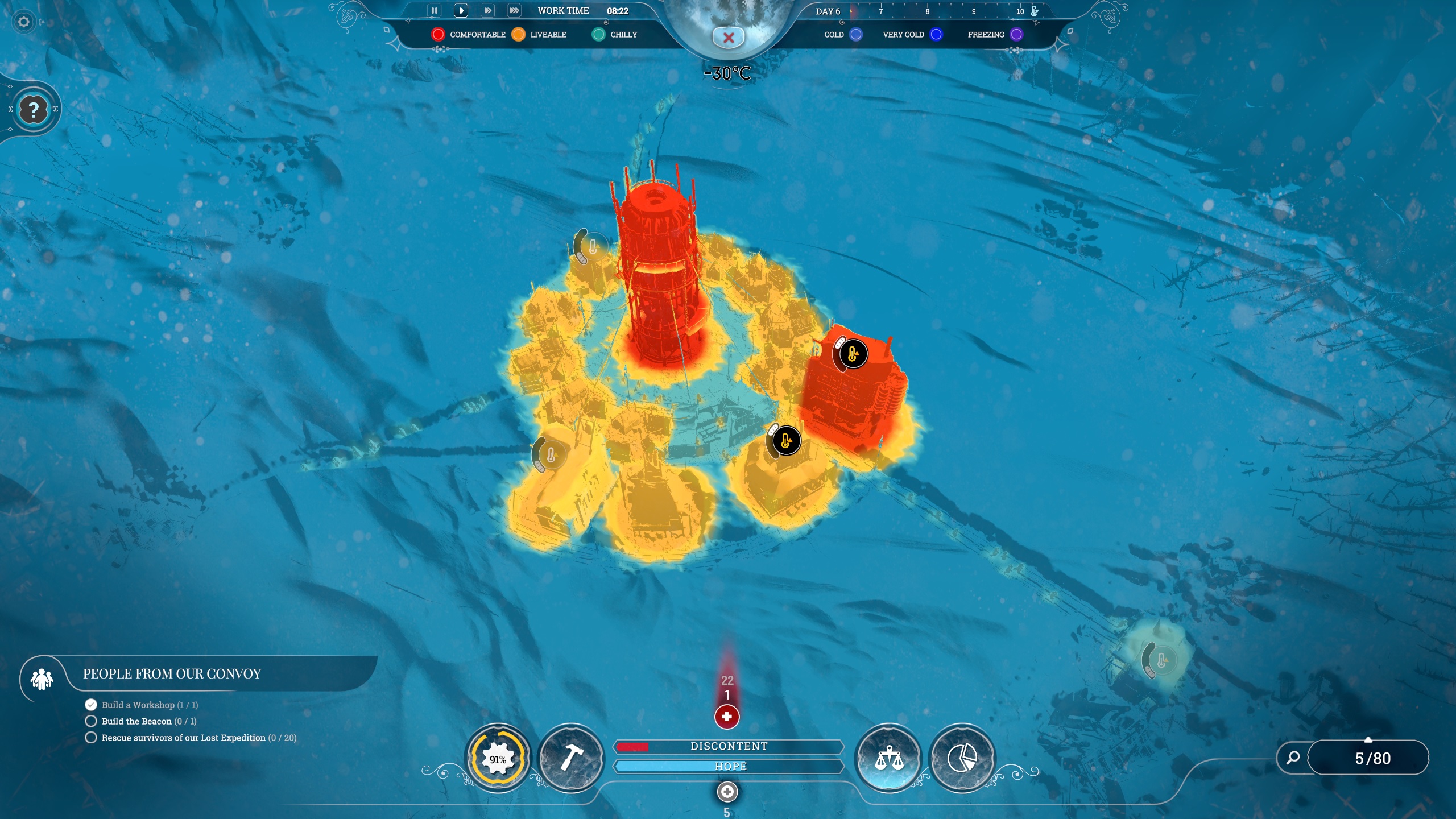
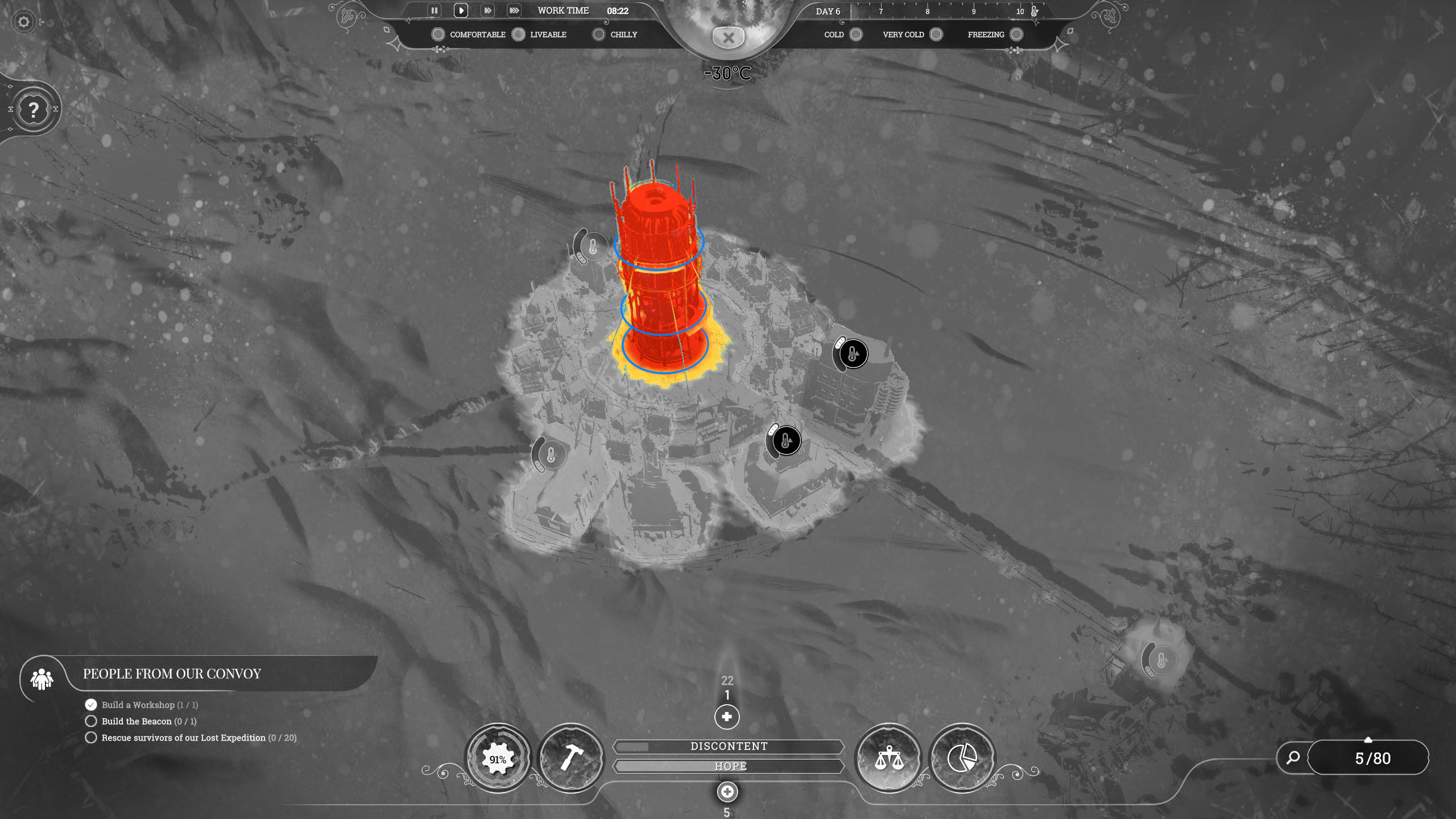
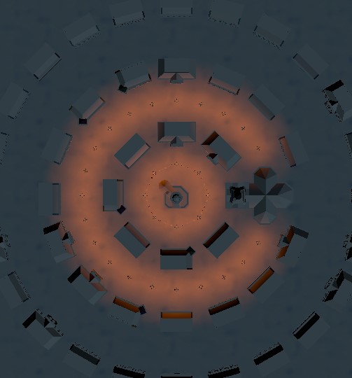
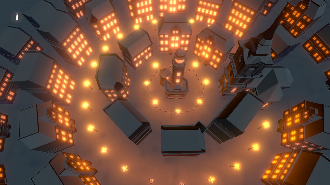
}Time to tackle the compute shader. Let’s take a step back and recap what we want to achieve with it. We want to create a texture that displays the buildings temperatures at the building’s positions. You can think of it as looking at the scene from the top like this:
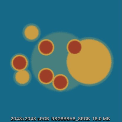
And we want to create a texture for this view that looks like this:
Open the “MaskCompute” shader in “Assets/Shaders”. We already looked at it in a previous chapter to talk about thread groups, so let’s talk about the two other things that are here.
#pragma kernel CSMainFirst, this line tells our compiler that our kernel function is called “CSMain”. It looks a bit silly since we are only having a single function in this shader, however we could potentially have hundreds of functions in here just like in any other shader and even multiple kernel functions.
void CSMain (uint3 id : SV_DispatchThreadID)The second thing I want to highlight is this ID parameter here. As you can see, it gets its value from the SV_DispatchThreadID system value. You might remember that I told you about the dispatch behaviour of compute shaders previously, and that they are dispatched in groups of 8x8 threads. Since we want to render to a texture here, we need to know where we are currently located on this texture. This is where the ID value comes into play. It is calculated by multiplying the thread group’s position with its size and adding the thread’s position from within the thread group. Since thread groups are 3-dimensional (in our case z is set to 1 so it is kind of only 2-dimensional) the ID is of type uint3 rather than uint (one ID per axis).
I know this all might sound a bit confusing, so here is quick example. Let’s assume our texture is of size 64x64. If our thread group size is 8x8, we need to dispatch 8x8 thread groups to render the whole texture.
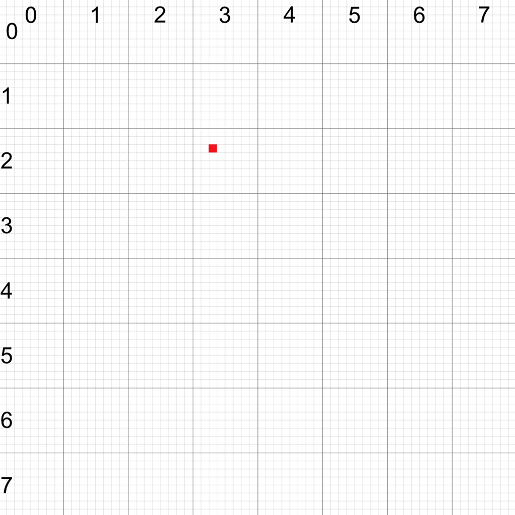
Let’s say we are currently at the red position and we want to render to this pixel. As mentioned, the ID is calculated by multiplying the thread group ID with its size and adding the thread ID. For the x axis, that gives us
ID.x = ThreadGroupID.x * ThreadGroupSize.x + ThreadID.x = 3 * 8 + 2 = 26
For the y axis we get
ID.y = ThreadGroupID.y * ThreadGroupSize.y + ThreadID.y = 2 * 8 + 2 = 18
Therefore, the id we get from SV_DispatchThreadID in this case would be (26, 18, 0).
With that out of the way, we can start coding. First, we have to add all the variables that we set up in the “MaskRenderer” script earlier. It is important that their names match the ones we have in the script.
+   int _BuildingCount;
+   int _TextureSize;
+   float _MapSize;
+   float _Blend;
Let’s start with the general variables. We add two integers for the amount of buildings in our compute buffer and for the size of the texture. We also need the size of the map to define how our buildings map onto the texture. Our texture always has the same size (uv coordinates from [0;0] to [1;1]), but it can cover a large area of our scene. How large this area is exactly is defined by this variable. Lastly there’s the blend variable used to determine the distance over which different colours for different temperatures are blend with each other.
+   float4 _Color0;
+   float4 _Color1;
+   float4 _Color2;
+   float4 _Color3;
We support 4 different temperatures in our setup. Each one needs its own colour which we are storing in those 4 variables.
+   Texture2D _NoiseTex;
+   SamplerState sampler_NoiseTex;
+   float _NoiseDetail;
We need to add some noise to the transition between colours to achieve the desired effect (as we discussed in the analysis section). Texture sampling in compute shaders is a bit more explicit compared to regular shaders as we need the texture und a separate SamplerState variable instead of a single sampler2D. The noise detail float determines the tilling of our noise texture.
+ StructuredBuffer<float> _BuildingBuffer;This structured buffer is the GPU equivalent of the compute buffer we set up for the building information. We set the compute buffer up to have 4 times the number of building elements and each element is a float value. This means this buffer contains the building information for the first building in the first 4 floats, for the second building in the 4 floats after that and so on.
+ RWTexture2D<float4> _Mask;The last variable here is the texture we are writing to. Compared to the noise texture, we have to mark this one as RW (read/write) and specify the type of each pixel (in our case a simple float4 value for a colour). Since we aren't reading from it (sampling it) we do not need a SamplerState here.
We now have everything we need to work on the CSMain function.
void CSMain (uint3 id : SV_DispatchThreadID)
{
+   float val = 0.0f;
}
Create a float variable for the heat value we calculate for the current pixel. This value will be somewhere between 0 and 1 and depending on it we’ll choose the right colour from the 4 provided ones at the end of the function. A value of 1 means we have the maximum temperature at the pixel, 0 means the minimum temperature.
void CSMain (uint3 id : SV_DispatchThreadID)
{
    float val = 0.0f;

+   float2 texelUVPos = id.xy / (float)_TextureSize;
+   float2 texelWorldPos = (_MapSize * texelUVPos) - (_MapSize * 0.5f);
}
In order to check the surrounding building for their temperature and painting that value onto the texture we need two positions. The first one is the uv coordinate of the pixel we are currently working on. We can calculate it by dividing our ID by the size of the texture. Going back to the previous example, the uv coordinate for our point at (26, 18) would be (0.41, 0.28) for a texture size of 64x64.
The second position is the current pixel's world position in our scene. Think of it as overlaying our scene with the texture and locating the current pixel in the world. We calculate this by simply scaling our texture by the size of the scene and moving it by half the size to centre it.
void CSMain (uint3 id : SV_DispatchThreadID)
{
    float val = 0.0f;

    float2 texelUVPos = id.xy / (float)_TextureSize;
    float2 texelWorldPos = (_MapSize * texelUVPos) - (_MapSize * 0.5f);

+   for (int i = 0; i < _BuildingCount; i++) {
+
+   }
}
Now that we have the positions, we can loop through all of our buildings and determine which one is in range and has the highest temperature.
void CSMain (uint3 id : SV_DispatchThreadID)
{
    float val = 0.0f;

    float2 texelUVPos = id.xy / (float)_TextureSize;
    float2 texelWorldPos = (_MapSize * texelUVPos) - (_MapSize * 0.5f);

    for (int i = 0; i < _BuildingCount; i++) {
+       float2 buildingWorldPos = float2(_BuildingBuffer[4 * i], _BuildingBuffer[4 * i + 1]);
+       float distance = length(texelWorldPos - buildingWorldPos);
    }
}
First, we have to get the position of the building we are checking. The position is stored in the first 2 of the 4 float values for the building and can simply be read from the buffer.
We can now calculate the distance between our pixel in world space and the buildings position to determine whether we are in range of it.
void CSMain (uint3 id : SV_DispatchThreadID)
{
    float val = 0.0f;

    float2 texelUVPos = id.xy / (float)_TextureSize;
    float2 texelWorldPos = (_MapSize * texelUVPos) - (_MapSize * 0.5f);

    for (int i = 0; i < _BuildingCount; i++) {
        float2 buildingWorldPos = float2(_BuildingBuffer[4 * i], _BuildingBuffer[4 * i + 1]);
        float distance = length(texelWorldPos - buildingWorldPos);

+       float heatVal = smoothstep(_BuildingBuffer[4 * i + 2] + _Blend, _BuildingBuffer[4 * i + 2], distance);
    }
}
We now need a function that returns 1 if our distance is smaller than the radius of the building and returns 0 if it is larger than the blend distance added to the radius of it. If our distance is in between those two values, we want it to blend smoothly between 0 and 1. Lucky for us, there already is such a function available in HLSL called smoothstep. The radius is stored in the third of the 4 float values for the building.
void CSMain (uint3 id : SV_DispatchThreadID)
{
    float val = 0.0f;

    float2 texelUVPos = id.xy / (float)_TextureSize;
    float2 texelWorldPos = (_MapSize * texelUVPos) - (_MapSize * 0.5f);

    for (int i = 0; i < _BuildingCount; i++) {
        float2 buildingWorldPos = float2(_BuildingBuffer[4 * i], _BuildingBuffer[4 * i + 1]);
        float distance = length(texelWorldPos - buildingWorldPos);

        float heatVal = smoothstep(_BuildingBuffer[4 * i + 2] + _Blend, _BuildingBuffer[4 * i + 2], distance);
+       val = max(val, heatVal * _BuildingBuffer[4 * i + 3]);
    }
}
Multiplying this smoothstep value with the temperature of the building (which is stored in the last of the 4 floats) gives us the final temperature for the pixel for this specific building. If it is higher than the previously stored temperature, we assign it to our final value. We can use the max() function for this. Frostpunk only ever displays the highest temperature rather than the sum of all temperatures.
void CSMain (uint3 id : SV_DispatchThreadID)
{
    float val = 0.0f;

    float2 texelUVPos = id.xy / (float)_TextureSize;
    float2 texelWorldPos = (_MapSize * texelUVPos) - (_MapSize * 0.5f);

    for (int i = 0; i < _BuildingCount; i++) {
        float2 buildingWorldPos = float2(_BuildingBuffer[4 * i], _BuildingBuffer[4 * i + 1]);
        float distance = length(texelWorldPos - buildingWorldPos);

        float heatVal = smoothstep(_BuildingBuffer[4 * i + 2] + _Blend, _BuildingBuffer[4 * i + 2], distance);
        val = max(val, heatVal * _BuildingBuffer[4 * i + 3]);
    }

+   val += _NoiseTex.SampleLevel(sampler_NoiseTex, texelUVPos * _NoiseDetail, 0).r * 0.05f;
}
Now that we have the highest temperature value for our position, we can add some noise to make the transitions less uniform. Sampling a texture in a compute shader is done by calling the SampleLevel() function of it. This function requires a sampler as the first argument, the uv coordinates and the second and the mipmap level we want to sample as the third parameter. Since we aren’t using any mipmaps this parameter is 0. Our uv coordinate is scaled by the noise tiling value. Our texture is stored as rgb but since we only need a single value from it we can pick any of the 3 channels (in our case r). The intensity of the noise cannot be larger than the step from one temperature to the next, as this would lead to weird results where a higher temperature is displayed in areas that aren’t heated. 0.05 is a reasonable value here.
Now that we have this value, we have to blend between the 4 provided colours.
void CSMain (uint3 id : SV_DispatchThreadID)
{
    float val = 0.0f;

    float2 texelUVPos = id.xy / (float)_TextureSize;
    float2 texelWorldPos = (_MapSize * texelUVPos) - (_MapSize * 0.5f);

    for (int i = 0; i < _BuildingCount; i++) {
        float2 buildingWorldPos = float2(_BuildingBuffer[4 * i], _BuildingBuffer[4 * i + 1]);
        float distance = length(texelWorldPos - buildingWorldPos);

        float heatVal = smoothstep(_BuildingBuffer[4 * i + 2] + _Blend, _BuildingBuffer[4 * i + 2], distance);
        val = max(val, heatVal * _BuildingBuffer[4 * i + 3]);
    }

    val += _NoiseTex.SampleLevel(sampler_NoiseTex, texelUVPos * _NoiseDetail, 0).r * 0.05f;

+   float4 col = lerp(_Color2, _Color3, smoothstep(0.55f, 0.75f, val));
+   col = lerp(_Color1, col, smoothstep(0.3f, 0.5f, val));
+   col = lerp(_Color0, col, smoothstep(0.05f, 0.25f, val));
}
We divide our calculated heat value (which ranges from 0 to 1) into 4 intervals, each one having a size of 0.2. In between those intervals we add smaller intervals of size 0.05 in which we blend between the colours. We can use the same smoothstep function as before to determine the lerp factor for each interval.
void CSMain (uint3 id : SV_DispatchThreadID)
{
    float val = 0.0f;

    float2 texelUVPos = id.xy / (float)_TextureSize;
    float2 texelWorldPos = (_MapSize * texelUVPos) - (_MapSize * 0.5f);

    for (int i = 0; i < _BuildingCount; i++) {
        float2 buildingWorldPos = float2(_BuildingBuffer[4 * i], _BuildingBuffer[4 * i + 1]);
        float distance = length(texelWorldPos - buildingWorldPos);

        float heatVal = smoothstep(_BuildingBuffer[4 * i + 2] + _Blend, _BuildingBuffer[4 * i + 2], distance);
        val = max(val, heatVal * _BuildingBuffer[4 * i + 3]);
    }

    val += _NoiseTex.SampleLevel(sampler_NoiseTex, texelUVPos * _NoiseDetail, 0).r * 0.05f;

    float4 col = lerp(_Color2, _Color3, smoothstep(0.55f, 0.75f, val));
    col = lerp(_Color1, col, smoothstep(0.3f, 0.5f, val));
    col = lerp(_Color0, col, smoothstep(0.05f, 0.25f, val));
+   _Mask[id.xy] = col;
}
The only thing that’s missing now is that we assign the final colour to the pixel in our output texture and we’re done with the compute shader. Now all we have left to do is to adapt our building shader to sample this texture when we are in heatmap mode. To do this, I’ll quickly introduce you to the concept of shader variants in the next chapter.
The final compute shader looks like this:
#pragma kernel CSMain

int _BuildingCount;
int _TextureSize;
float _MapSize;
float _Blend;

float4 _Color0;
float4 _Color1;
float4 _Color2;
float4 _Color3;

Texture2D _NoiseTex;
SamplerState sampler_NoiseTex;
float _NoiseDetail;

StructuredBuffer<float> _BuildingBuffer;

RWTexture2D<float4> _Mask;

[numthreads(8,8,1)]
void CSMain (uint3 id : SV_DispatchThreadID)
{
    float val = 0.0f;

    float2 texelUVPos = id.xy / (float)_TextureSize;
    float2 texelWorldPos = (_MapSize * texelUVPos) - (_MapSize * 0.5f);

    for (int i = 0; i < _BuildingCount; i++) {
        float2 buildingWorldPos = float2(_BuildingBuffer[4 * i], _BuildingBuffer[4 * i + 1]);
        float distance = length(texelWorldPos - buildingWorldPos);

        float heatVal = smoothstep(_BuildingBuffer[4 * i + 2] + _Blend, _BuildingBuffer[4 * i + 2], distance);
        val = max(val, heatVal * _BuildingBuffer[4 * i + 3]);
    }

    val += _NoiseTex.SampleLevel(sampler_NoiseTex, texelUVPos * _NoiseDetail, 0).r * 0.05f;

    float4 col = lerp(_Color2, _Color3, smoothstep(0.55f, 0.75f, val));
    col = lerp(_Color1, col, smoothstep(0.3f, 0.5f, val));
    col = lerp(_Color0, col, smoothstep(0.05f, 0.25f, val));
    _Mask[id.xy] = col;
}So, let’s talk about how we can use one shader for our buildings and switch between the regular view and the heatmap view. Intuitively, we could add a variable and add a simple if/else statement to switch between the views based on it. While this would work it is not really efficient to do so. The best way to handle such a situation is by creating two different versions of a shader and selecting the right one at runtime. Those versions are called shader variants. You might have seen them before without paying too much attention to them. When you build a Unity project using the standard shader, a ridiculous amount of shader variants gets build for it (usually over 1000). This is due to the large complexity of the standard shader and the many use cases it has to support while still maintaining a high level of performance.
There are compiler directives for creating shader variants:
#pragma multi_compile
#pragma shader_feature
For each shader variant a keyword is added to the pragma. The compiler will create the variants with the defined keywords for us. The main difference between the two directives is the way the shader variants are handled in builds. Unity will strip unused variants from the build if they are created using shader_feature. On the other hand, multi_compile variants will always be included. As a result, multi_compile should be used whenever a keyword can change during runtime, e.g. by changing it from a script and shader_feature should be used for values that don’t change, e.g. material toggles. We’ll implement an example for both so you can see the difference in practice.
If you would like to learn more about shader variants, you should take a look at Unity’s documentation.
Let’s start with the shader_feature. In this example, we’ll add a simple toggle to the properties that allows us to disable the snow effect in the building shader.
Properties
{
    _MainTex("Texture", 2D) = "white" {}
    [HDR]_Emission("Emission", Color) = (0.0, 0.0, 0.0, 0.0)
+   [Toggle(ADD_SNOW)] _Snow("Add Snow", Float) = 0
    _SnowColor("Snow Color", Color) = (1.0, 1.0, 1.0, 1.0)
    _SnowAngle("SnowAngle", float) = 0.0
}
Material toggles in Unity are simply float values that are either 0 or 1. By adding the toggle drawer to it we tell Unity that we want to display this float value as a toggle rather than the usual numeric field. The toggle drawer requires a keyword as parameter. This keyword will be defined if the toggle is set. In our case I decided to call the keyword “ADD_SNOW”.
Pass
{
    Tags {"LightMode" = "Deferred"}
    HLSLPROGRAM

+   #pragma shader_feature ADD_SNOW
Next, we have to add the compiler directive that adds the additional shader variant. We now have our default shader variant and one variant where “ADD_SNOW” is defined, i.e. our toggle in the properties is set.
+   #if defined(ADD_SNOW)
        float normalDot = dot(i.normal, float3(0.0f, 1.0f, 0.0f));
        if (normalDot < _SnowAngle)
            o.albedo = tex2D(_MainTex, i.uv);
        else
            o.albedo = _SnowColor;
+   #else
+       o.albedo = tex2D(_MainTex, i.uv);
+   #endif
The last thing we have to do is check whether the keyword is defined and change the behaviour of the shader accordingly. In our case I’ll simply write the colour texture to the albedo G-Buffer all the time instead of writing the snow colour if the keyword is not set.
If you’ve done everything correctly you should now be able to toggle the snow effect using the checkmark in the various materials.
Alright so let’s add support for our heatmap view next. The “HeatViewController” script enables and disables a keyword in our material called “RENDER_HEAT” at runtime. This is a typical use case for the multi_compile directive.
    #pragma shader_feature ADD_SNOW
+   #pragma multi_compile __ RENDER_HEAT
With this line we are telling the compiler that we want two variants of the shader, one with the “RENDER_HEAT” keyword enabled and one without. Since the number of keywords Unity can support at once is limited, it is a good practice to use “__” as keyword for the default shader variant. This won’t create a new keyword but rather handle the case that none of the other keywords are enabled.
+   #if defined(RENDER_HEAT)
+
+   #else
        #if defined(ADD_SNOW)
            float normalDot = dot(i.normal, float3(0.0f, 1.0f, 0.0f));
            if (normalDot < _SnowAngle)
                o.albedo = tex2D(_MainTex, i.uv);
            else
                o.albedo = _SnowColor;
        #else
            o.albedo = tex2D(_MainTex, i.uv);
        #endif
        o.specular = float4(0.0f, 0.0f, 0.0f, 0.0f);
        o.normal = float4(i.normal * 0.5f + 0.5f, 0.0f);
        o.emission = _Emission;
+   #endif
We can now check if the keyword is defined and only write the previous result to the G-Buffer if that is not the case. In case that it is, we want to sample our heatmap texture and return that colour as albedo. In order to be able to do this we need a few things first.
struct v2f
{
    float4 vertex : SV_POSITION;
+   float3 worldPos : TEXCOORD1;
    float3 normal : NORMAL;
    float2 uv : TEXCOORD0;
};
Since we are sampling the texture based on the world position of our fragment, we need to give this information to our fragment shader by adding it to the v2f struct.
v2f vert (appdata v)
{
    v2f o;
    o.vertex = UnityObjectToClipPos(v.vertex);
+   o.worldPos = mul(unity_ObjectToWorld, v.vertex);
    o.normal = UnityObjectToWorldNormal(v.normal);
    o.uv = TRANSFORM_TEX(v.uv, _MainTex);
    return o;
}
Lucky for us, we don’t need additional vertex data in our vertex shader, as we can simply calculate the world position for a vertex by multiplying its object position with the object-to-world matrix.
+   sampler2D _Mask;
+   float _MapSize;
In order to be able to sample our texture we first need a sampler2D variable for it, as well as the size of our scene in the shader. If you remember the “MaskRenderer” walkthrough from earlier, you already know that those variables are global shader variables. As long as they are called “_Mask” and _”MapSize” they’ll get their values automatically assigned by the render backend.
#if defined(RENDER_HEAT)
+   float4 mask = tex2D(_Mask, i.worldPos.xz / _MapSize + 0.5f);
#else
We can now easily sample our heatmap texture. Since we are sampling in uv space we have to first map our world position’s x and z coordinates to it. That’s why we need to know how much area in our world is covered by the texture.
#if defined(RENDER_HEAT)
    float4 mask = tex2D(_Mask, i.worldPos.xz / _MapSize + 0.5f);
+   o.albedo = float4(mask.rgb, 1.0f);
+   o.specular = float4(0.0f, 0.0f, 0.0f, 0.0f);
+   o.normal = float4(i.normal * 0.5f + 0.5f, 0.0f);
+   o.emission = float4(0.0f, 0.0f, 0.0f, 1.0f);
#else
We can now fill the G-Buffer the same way we did before. Instead of writing a colour from the main texture or the snow colour to the albedo target, we’ll write the colour from the heatmap texture. We don’t want our emissive surfaces to glow in that view, so we’ll set the emissive colour to black. The normal and specular values don’t change.
And with that we are done with the basic effect in this tutorial. The scene looks a little bit flat at the moment, to fix this we’ll add some post-processing in the next chapter.
The basic post-processing setup is already prepared in the template project. I am using the Unity’s Post-Processing stack v2, which you can get from the package manager.
To get started, select the main camera and scroll down in the inspector to see the post-process volume component. Make sure to activate it. We can now use the “Add effect…” button to add a variety of post-processing effects.
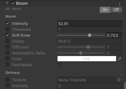
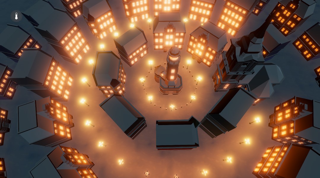
The first effect I’m adding here is bloom. It makes the emissive surfaces illuminate the surrounding areas of the screen and make it appear as if the windows of the buildings illuminate the area in front of the buildings. I’m setting the intensity of the effect to quite a high value and I'm tweaking the soft knee option to control the range.
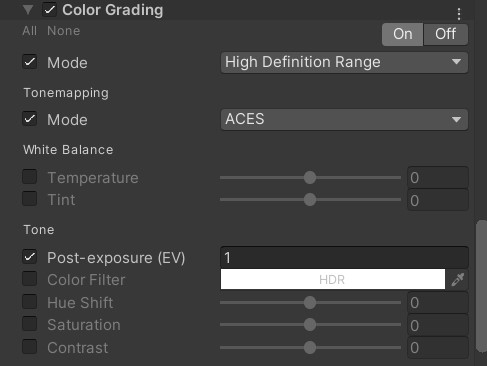
I’m using colour grading for ACES tonemapping. Depending on your taste, you might prefer neutral tonemapping instead, as ACES results in a more cinematic look. Due to the scene being a bit dark I added some post exposure.
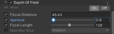
Depth of field gives our scene this unique miniature look. The focus distance depends on the distance of the camera to the scene and a value around 45 yields the best results for me. Depending on the strength of the blur you want to achieve you should change the other settings.
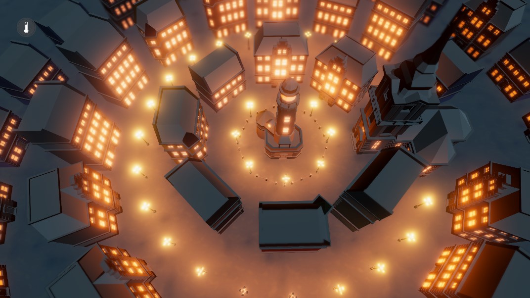
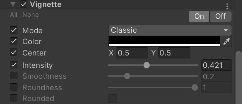
The last effect I’m adding is a vignette. The vignette allows me to darken the outer areas of the scene to focus on the lit area.
I’m not really a talented artist, so you should play around with the various settings and try to create your own unique look for the scene. There’s probably a lot of room for improvements here. Make sure to share your results with me on Twitter or Discord. You can see the final look of my scene in the video at the end of the tutorial.
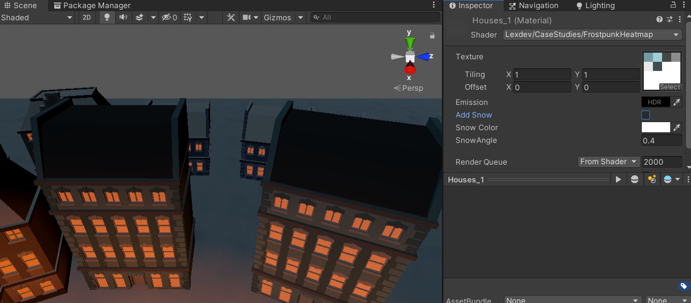
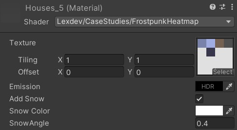
As usual, here are the material setups in the final version of the project. For the different house materials, I chose 0.4 as snow angle and made sure to set the toggle to enable it. The snow colour is set to almost full white and the emission is set to black with 0 intensity. We don’t really want our buildings to glow.
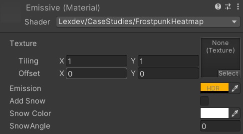
Make sure to deactivate the snow toggle for the ground, emissive and glass materials. For the ground we are already using a snow texture and we don’t want snow on our windows and on the lamps. You should play with the emissive colours of the lamps and the glass if you want them to be less emissive or have a warmer/cooler colour.
And that’s all for this one! I hope you learned a thing or two while working through all of this, given the length of the tutorial I’m certainly impressed that you made it to the end at all. As usual, here’s the link to the final version of the project:
Final ProjectYou should try to expand the effect and add additional stuff on your own, if you do make sure you share it with me via Twitter, Reddit or Discord. By the way, you should totally join our discord community if you haven’t and follow me on twitter for updates and news. If you would like to see a specific tutorial in the future, you can suggest it to me there as well!
Lastly, consider supporting me on Patreon if you enjoyed this tutorial or the others on the site. It takes a lot of time to create each one of them and your support allows me to keep the site free for everyone and without ads. Thank you so much!
Get the tutorial project from GitHub - It contains all the assets necessary to achieve the final result!
Help me to create more amazing tutorials like this one by supporting me on Patreon!
Make sure to follow me on Twitter to be notified whenever a new tutorial is available.
If you have questions, want to leave some feedback or just want to chat, head over to the discord server! See you there!
Projects on this page are licensed under the MIT license. Check the included license files for details.

If you like the tutorials and want to support me, head over to Patreon to do so! You'll also get access to some amazing perks like special discord roles with priority support!
I'd like to get in touch and read what you think about the site.
Feedback is always appreciated!
Feel free to send me suggestions for future tutorials.
Questions and messages from patrons will be answered with a higher priority!