GitHub
Get the tutorial project from GitHub - It contains all the assets necessary to achieve the final result!
Even though it looks a bit complicated, the shader used in Overwatch on the shields is quite simple and easy to create. We'll look at how to implement neat features like the depth-based intersection and different optimisation techniques for the shader. In this tutorial we'll recreate Reinhardt's version of it. However, once you understand how everything works you can easily transfer your knowledge to another version of the shader as well, e.g. Winston's and Brigitte's shield.
You should be able to follow this tutorial without prior shader knowledge; however, I recommend starting with a beginner tutorial. I tried to keep this tutorial easy enough for beginners to follow, thus it became pretty damn long (sorry for that). If you are a more advanced shader programmer, you'll hopefully be able to skip to the parts that are interesting for you.
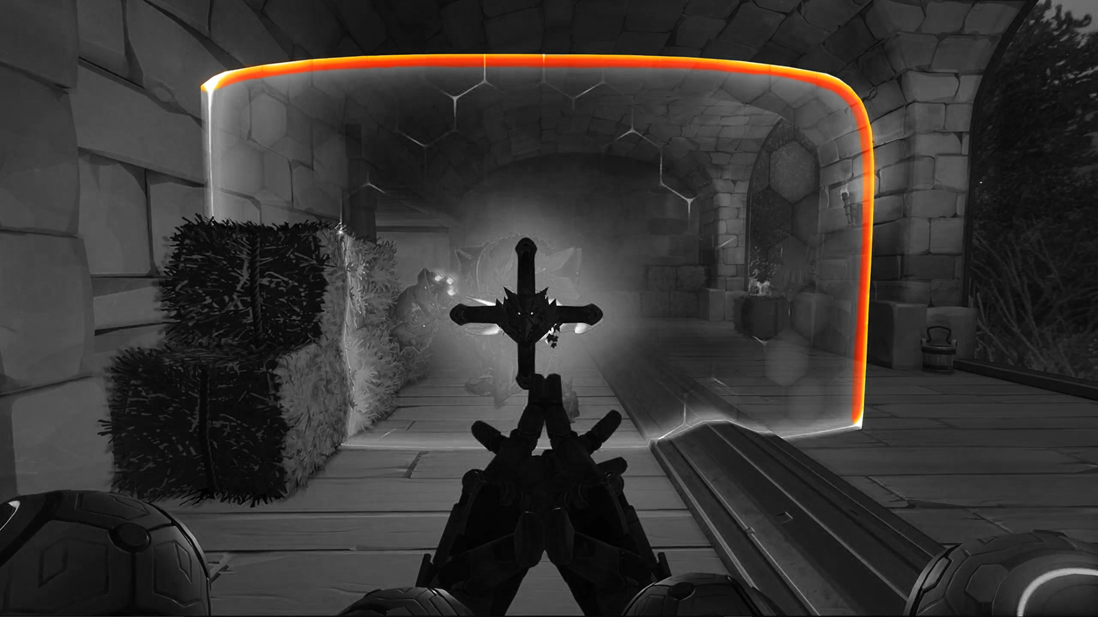
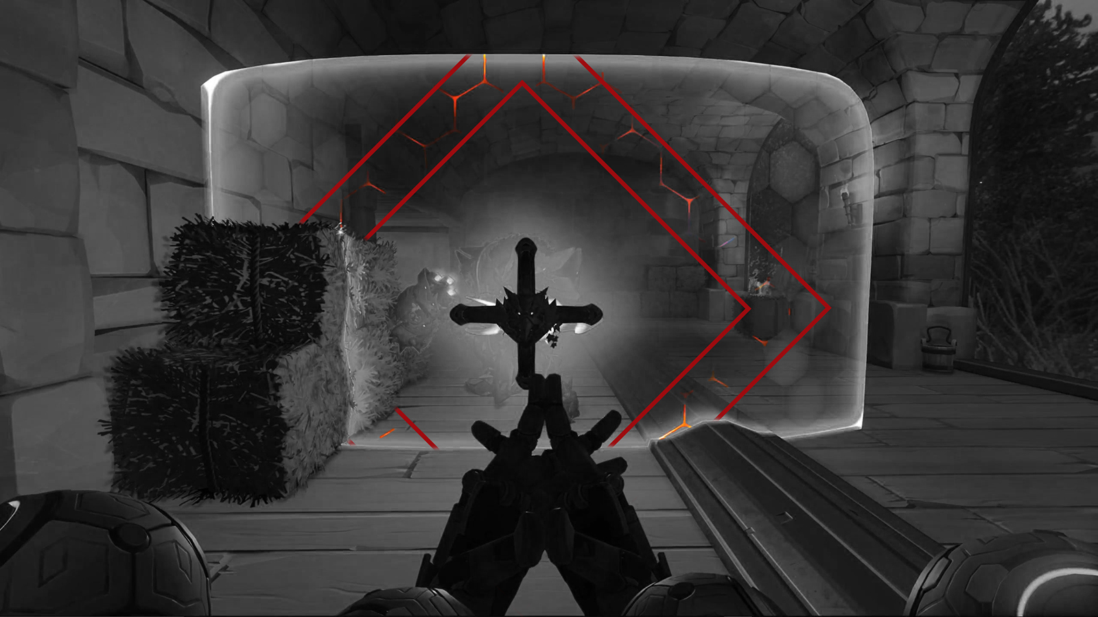
Alright, so let's start by analysing the shader in-game. Each case study begins by just playing the game and paying special attention to the shaders and effects you want to implement. There's a practice mode in Overwatch where you can take all the time you need. I jumped into said mode with a friend to check out the shader in detail. For convenience, I recorded a short video of it on Reinhardt's shield which shows the enemy's version of it (red version).
Take a moment and think about which components make up the final effect.
...
Got all of them? Good! Let's take a closer look.
Let's get the obvious parts out of the way first. We do have a transparent shield and a base colour, which allows us to for example switch between the friendly (blue) and the enemy (red) version. If we move around the shield, we can also see that back-face culling is disabled.
"Culling" is the term used to describe the process of skipping/discarding objects during rendering. The most common culling methods are frustum culling (only rendering objects in the camera's view frustum), occlusion culling (prevent occluded objects from being drawn) and back-face culling. Back-face culling assures, that only triangles that face the camera (normal pointing towards the camera) are being drawn.
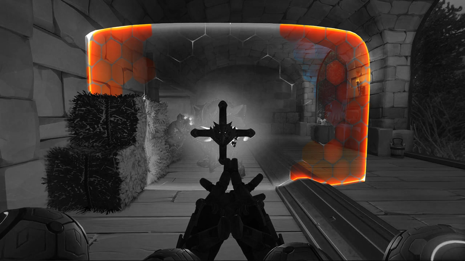
The first major component is the animated hex fields. They pulsate from the centre outwards along the x-axis. If you look closely you can see that each field adds a random offset to the basic wave. Thus, the fields appear to be more random than they are, the offset is identical for each cycle of the wave. This might sound a bit complicated at the moment, but trust me, once we implement it, it makes perfect sense.
Next up, we have another pulse. This time it's a simple diamond pattern with increasing size, highlighting the edges of the hex fields. As a result we get this effect, which looks as if the highlights are following the edges towards the corners of the shield.
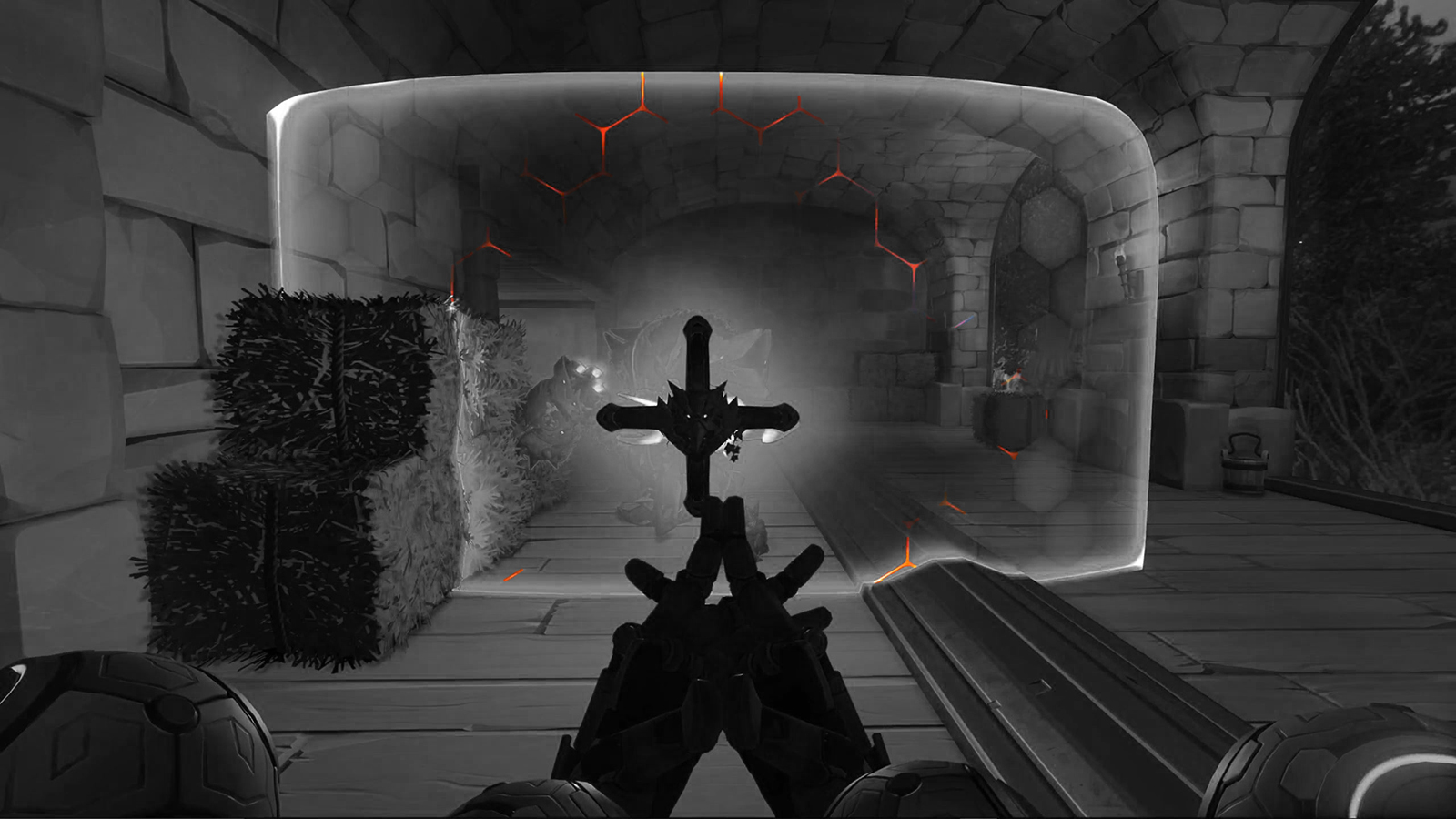
Finally, we have the bright edge of the shield. If you look closely you realize that it's actually two different effects, the outer edge of the shield and an intersection highlight.
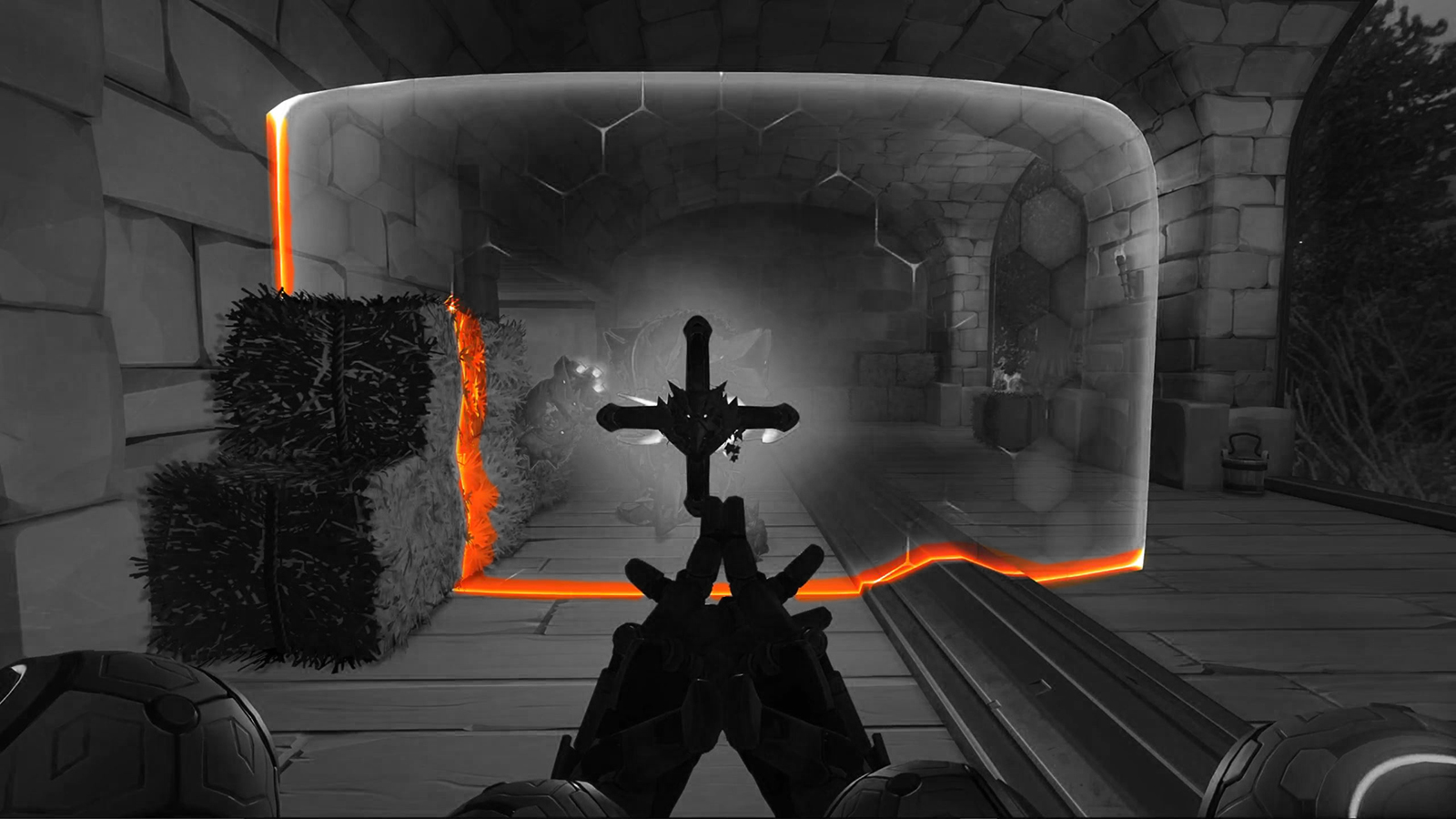
You can clearly see the intersection highlights when watching the cart drive through the shield. We can use the depth values to calculate those intersections (more on that later). For now, let's get started and set everything up.
Instead of starting with a fresh, empty project I decided to provide a template project for this tutorial. It contains models, materials, textures, scripts and the scene you can see in the final version. Start by downloading or cloning the repository from GitHub.
Template Project
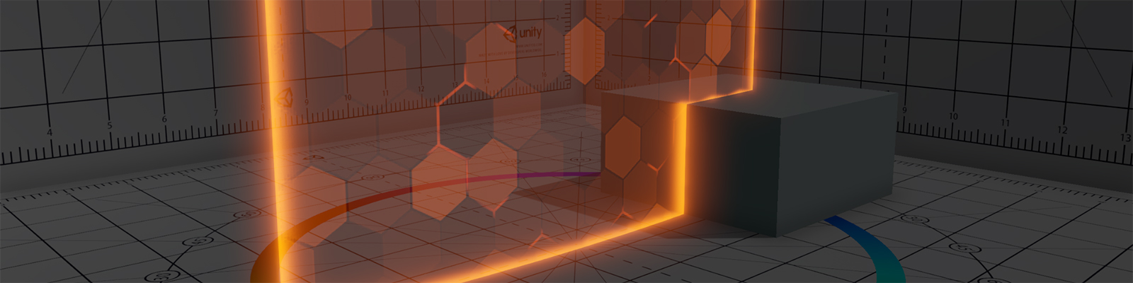
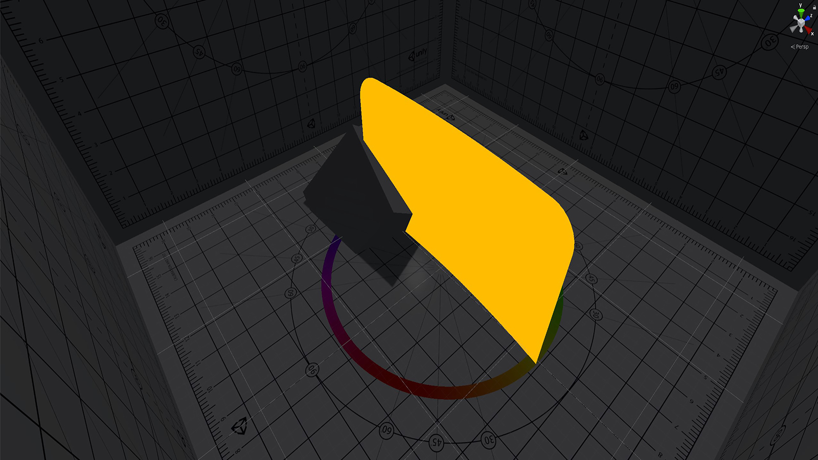
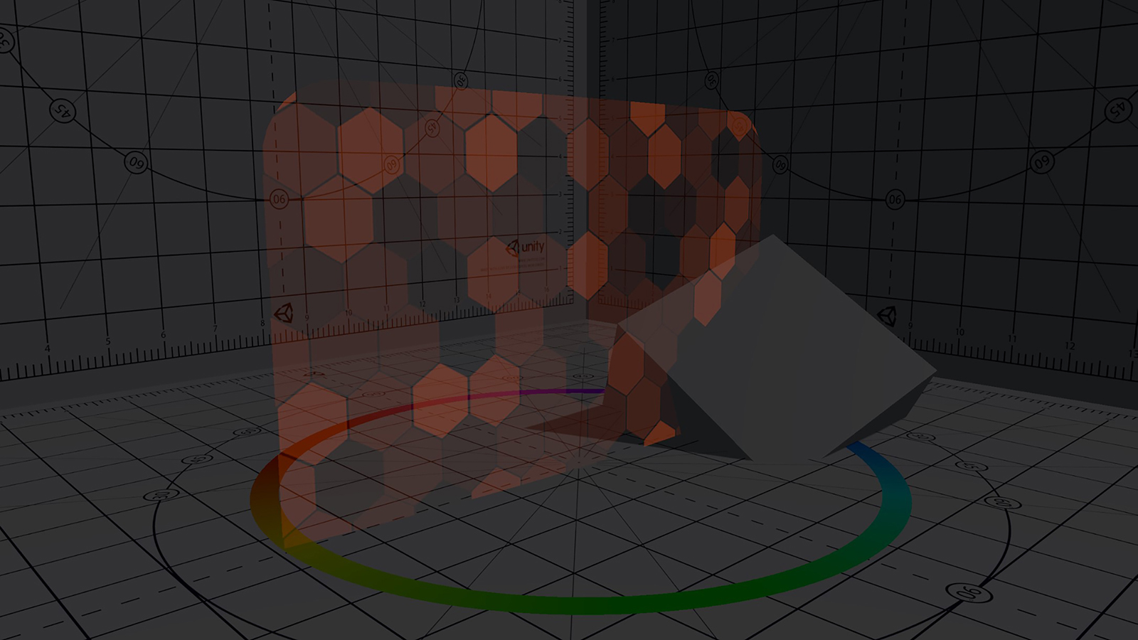
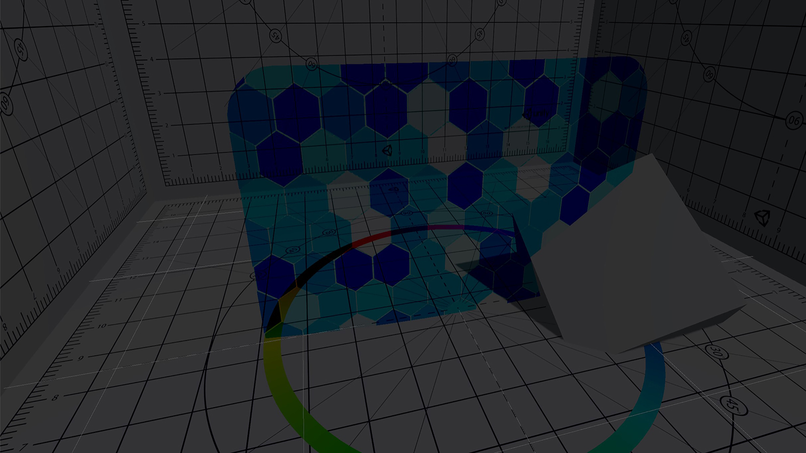
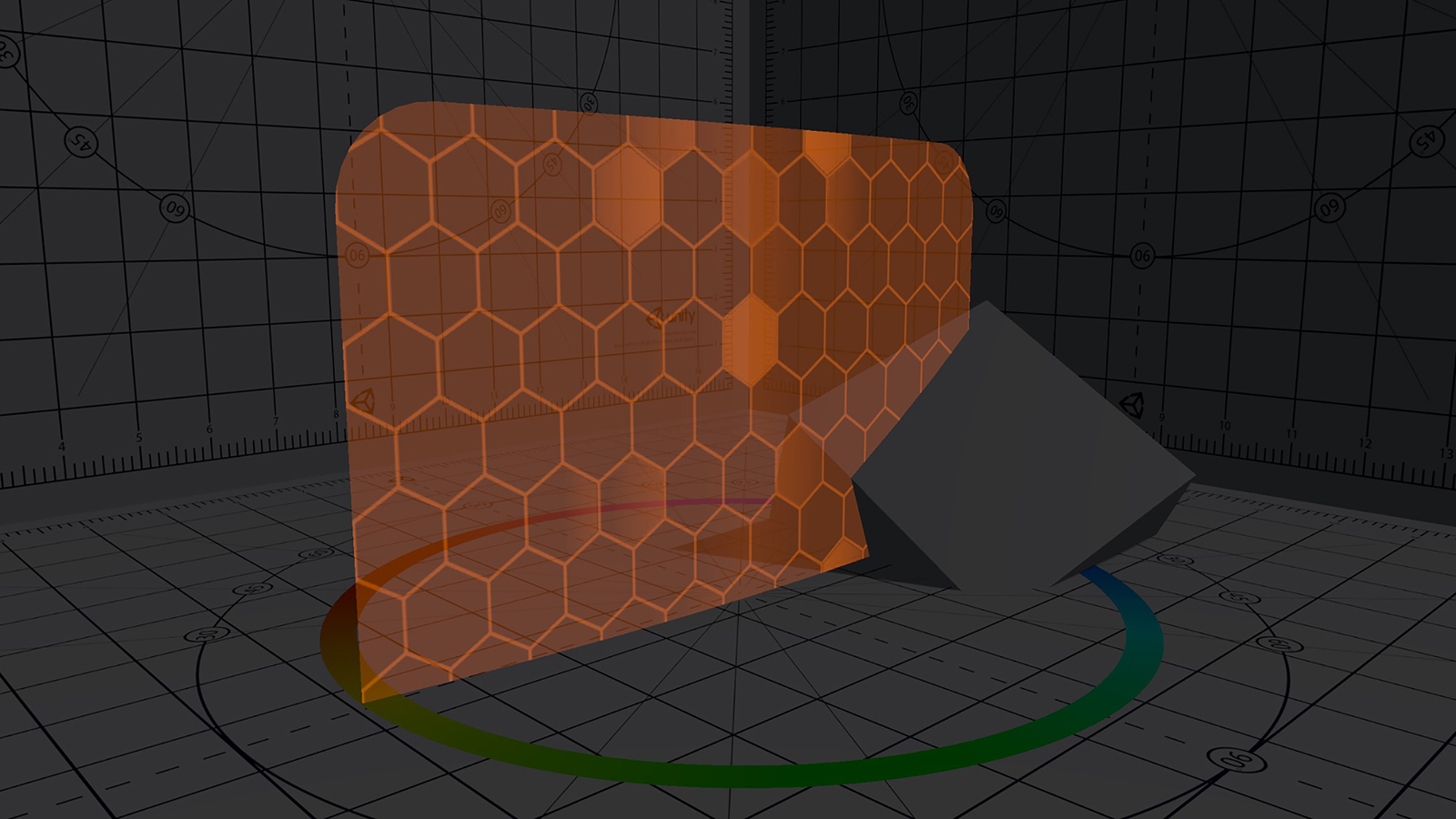
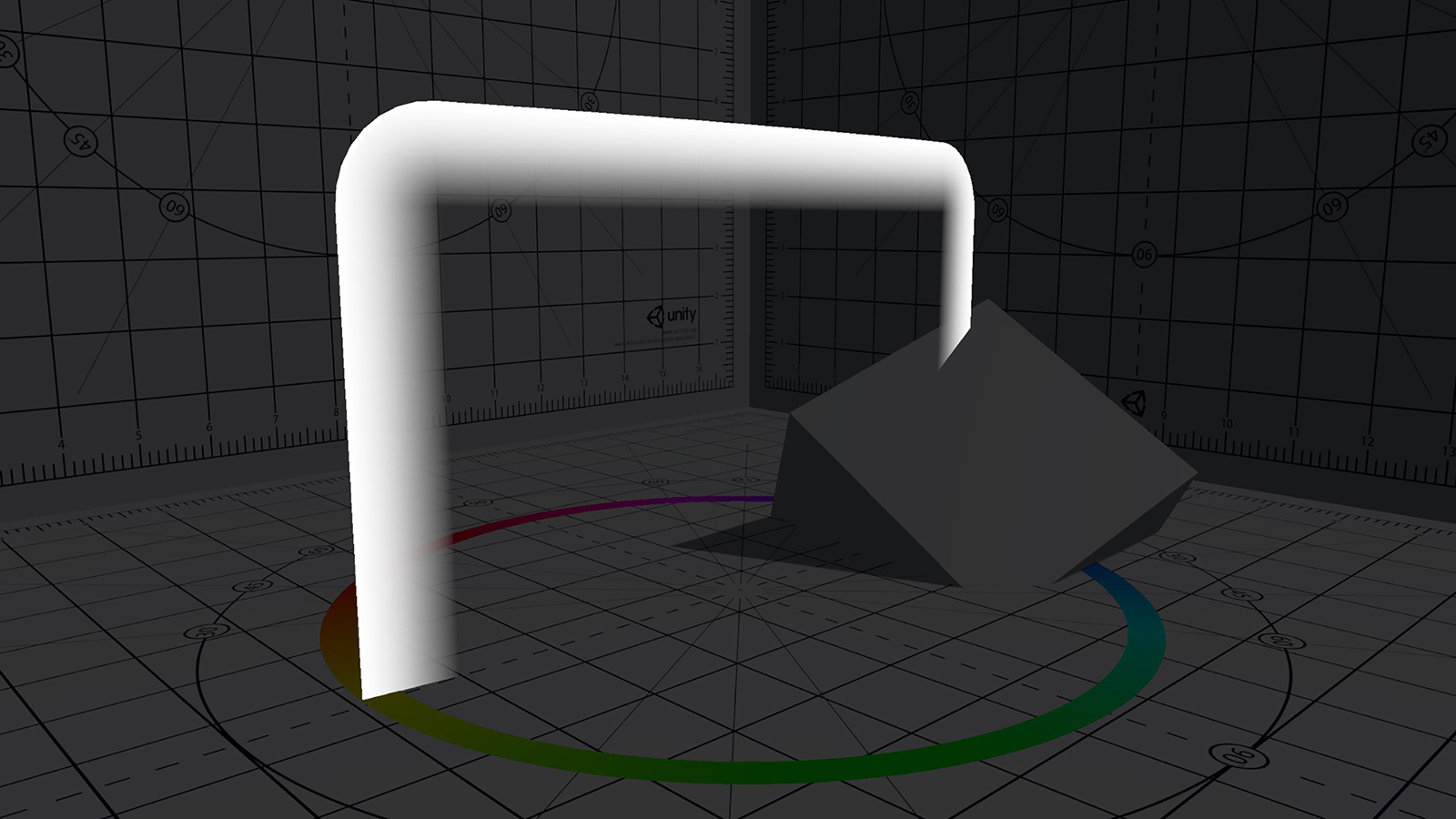
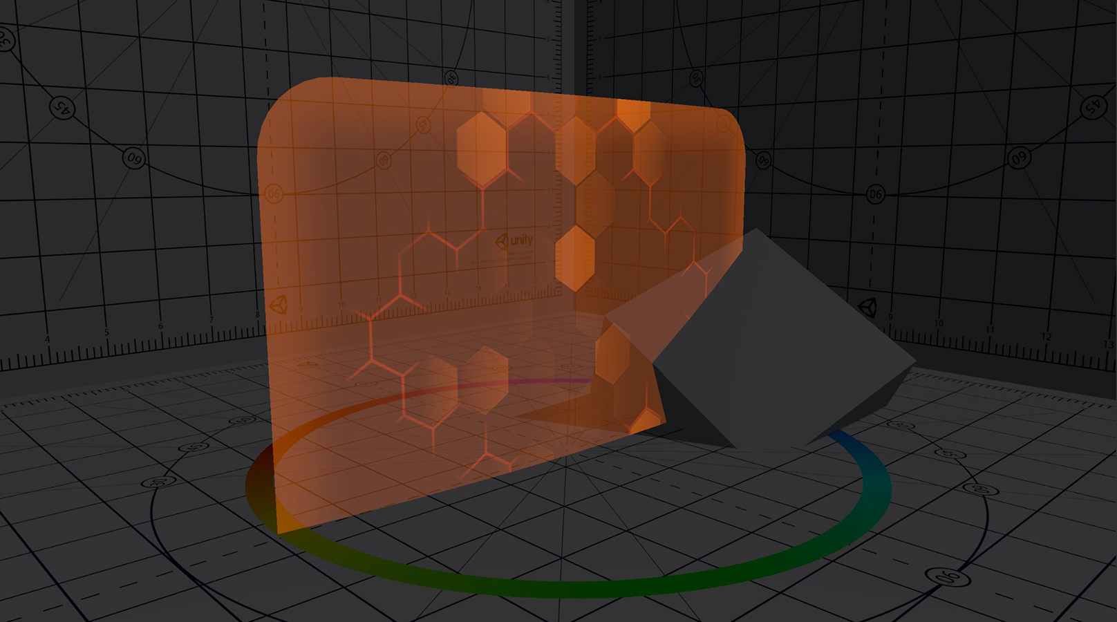
Open the project and the CalibrationScene in “Assets/Scenes”. You should see the following image:
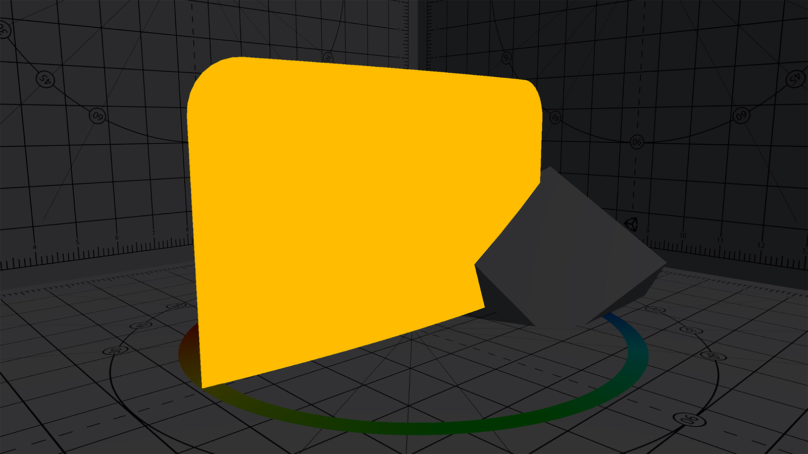
As you can see, I already prepared a simple shader for the shield which just returns a single colour. We’ll expand this one in the next chapters. For the background, I used parts of Unity’s old shader calibration scene which is a nice background for shader projects. Additionally, I added a simple cube to test our intersection highlight later.
If you enter the play mode, the shield model should rotate around the y-axis. Since the object is basically just a bent plane without any volume, you can’t see it from behind. This is due to the previously mentioned backface culling.
One more thing about the template project I want to highlight is that I set the project’s colour space to linear.
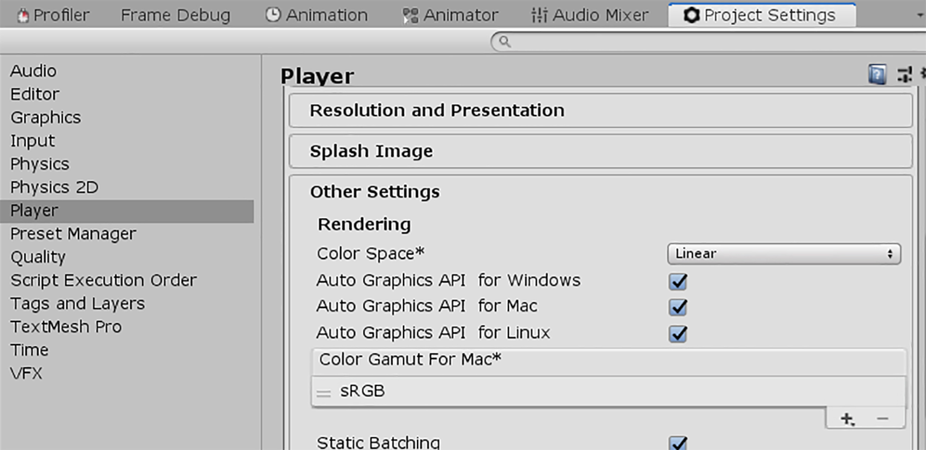
Modern physically based rendering is usually done in linear colour space, since it is required for more accurate results. I usually only work in linear space to assure that all my shaders are compatible between projects and to future proof them.
If you want to learn more about colour spaces, check out this awesome article on kinematicsoup or look at Unity’s documentation.
Before adding our own code, we should look at the existing shader. You can find it in “Assets/Shaders”, go ahead and open it up in your editor of choice.
Let’s look at what’s already in there. It’s a simple, basic shader that only returns a single colour, however I want to use this opportunity to describe the basic components of the shader in more detail. You can skip to the “Writing custom code” section if you already know about that stuff.
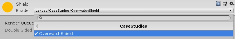
Shader "Lexdev/CaseStudies/OverwatchShield"The string parameter in the first line of the shader allows you to adjust the path of the shader file, e.g. the path visible when selecting a shader for a material. You can change this to whatever you want or just leave it as is.
This first line is part of the ShaderLab code in our file, a language designed by Unity.
Every shader file in Unity requires a wrapper written in the ShaderLab language. This wrapper helps you integrate your actual GLSL, HLSL or CG shader code into Unity. Inside the ShaderLab code you can define properties that should be visible in the Unity inspector, different shader versions used for different target platforms, fallback shaders and more.
Check out the documentation for more information.
Properties
{

}
Since the output colour is hard coded into the fragment function, there aren’t any properties necessary to achieve the current result of the shader. We’ll add a lot of properties here during this tutorial to make it easy to adjust the look of the shader later in the Unity editor without having to change the code.
SubShader
{
    Pass
    {
    }
}
Next up we have our subshader. Your shader file can contain multiple subshaders, with multiple passes inside of them. Unity will always pick the first subshader capable of running on your target platform or, if none of your subshaders work, the fallback shader you defined. This allows you to support vastly different target platforms with just one shader file, which means you don’t have to change all materials, even if you build the same project for e.g. PC and mobile. + I didn’t define a fallback shader here since it’s easier to develop without one, if there’s an error you should see the wrong result.
HLSLPROGRAM

ENDHLSL
The HLSLPROGRAM and ENDHLSL keywords define the block inside of which the actual shader code is located. This is the part of your shader file that contains the logic, remember the ShaderLab wrapper is just there to handle different shader versions and show your properties in the inspector.
Instead of HLSLPROGRAM and ENDHLSL you can also use CGPROGRAM and ENDCG or GLSLPROGRAM and ENDGLSL. If you work with a custom renderer it matters which shader language you are using (GLSL for OpenGL/Vulkan, HLSL for DirectX, CG is deprecated and shouldn’t be used at all anymore), however Unity handles a lot of those issues for us. I generally recommend using HLSL for your shaders (HDRP and LWRP/URP shaders are all written in HLSL) except for surface shaders, where you must use CG (There is no surface shader support for the scriptable render pipelines).
Even though HLSL shaders are only supported by DirectX renderers, Unity handles the translation for other platforms for you. How Unity translates your shader depends on the target rendering backend, if you are interested in the details you can find more information in the documentation.
#pragma vertex vert
#pragma fragment frag
This part of the code defines the vertex and the fragment function of the shader pass. Each pass must have exactly one of each, it can however have additional functions e.g. for a geometry shader.
The syntax for those function definitions is
#pragma [FunctionType] [FunctionName]Vert and frag are usually chosen as the names for the vertex and fragment functions.
#include "UnityCG.cginc"The include keyword in shaders works like the include keyword in C-like languages. It allows us to use the functions, constants, macros and structs defined in the header file. This specific header file is usually included in every Unity shader, it contains lots of helpful functions like commonly used matrix multiplications.
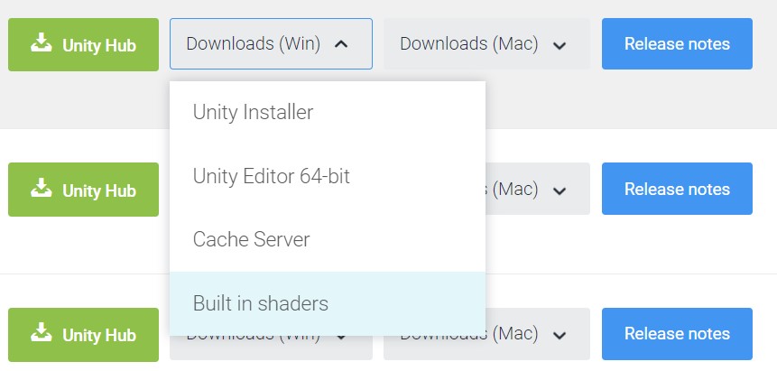
You can download Unity’s built-in shader files from the Unity download archive by opening the dropdown menu for a platform and choosing built-in shaders.
You can find "UnityCG.cginc" inside the “CGIncludes” folder.
struct appdata
{
    float4 vertex : POSITION;
};
The appdata struct is used as the input parameter for the vertex function. It contains variables for the vertex data we want to use in our shader. The name “appdata” is commonly used, you can also find some predefined structs for this in UnityCG.cginc (e.g. appdata_base). The syntax for the variables of the struct is:
[Type] [Name] : [Vertex Attribute];In addition to the position, a lot of other data is usually stored in a mesh. Commonly used vertex attributes are:
POSITION, COLOR, TEXCOORD0, TANGENT, NORMAL
For more details take a look at the documentation.
struct v2f
{
    float4 vertex : SV_POSITION;
};
The v2f struct is the return type of the vertex function and the input parameter of the fragment function, hence the name “v2f” (vertex to fragment). For the GPU rasterizer to know which variable contains the vertex position (in clip space), it must be of type float4 and marked with SV_POSITION. The rasterizer then generates the fragments based on this. You can add additional variables to this struct, just keep in mind that they’ll be interpolated across each triangle based on the output of the 3 vertices’ vertex functions.
During the rasterization stage, the GPU calculates which pixel is covered by each triangle. For an in depth description, check out these slides.
v2f vert (appdata v)
{
    v2f o;
    o.vertex = UnityObjectToClipPos(v.vertex);
    return o;
}
As described before, the vertex function requires an appdata struct as parameter, and a v2f struct as return type. In this simple shader, the only thing we must do is transform the vertex position (which is in object space) into clip space. This can be done by multiplying it with the model matrix (to convert it to world space), then the view matrix (to convert it to camera space) and afterwards with the projection matrix (to convert it to clip space). UnityCG.cginc contains a simple function called UnityObjectToClipPos, which does exactly that for us. We then write the converted vertex position into the output struct’s vertex variable and return it. While this is quite a basic vertex function it's all we need at the moment to achieve the current result.
fixed4 frag (v2f i) : SV_Target
{
    return fixed4(1.0f,0.5f,0.0f,1.0f);
}
The last part is the fragment function, which simply returns a fixed4 variable.
Depending on the type of data you want to save in your variable you might want to choose fixed or half instead of float (or fixed4/half4 instead of float4) to optimise your shader. For non-HDR colours, fixed is plenty of precision. As with most shader topics, you can read more about it in the documentation.
The output variable is also marked with SV_TARGET, which works like SV_POSITION but contains the colour value for the fragment instead of the vertex position. As a return value, I just hard coded the colour orange for now. We'll replace that in the next section.
Alright, now that we’ve got the existing shader out of the way, let’s finally start by writing our own code and implementing the different components to achieve the final shield effect.
Let’s start by implementing three simple things: Disabling backface culling, making the shield transparent and adding a variable for the shield colour so we can adjust it (and its alpha value) in Unity.
Disabling backface culling is easy, all we need to do is add
Cull Offto our subshader block in front of the pass. This disables backface culling for all objects with this material. If you switch back to Unity, you should now be able to see the shield from all sides.
The default value for Cull is Back, which leads to triangles not being drawn if their normal is facing away from the camera (backface culling). Alternatively, you can set Cull to Front for frontface culling, or Off to disable it.
Next up is transparency. In order to make a shader transparent, you must define three things in your shader: The render queue position, the render type and the blend mode. Queue and type both need to be set to Transparent, and both are set by adding tags to the subshader (right next to the cull options):
Tags {"RenderType" = "Transparent" "Queue" = "Transparent"}The type is actually optional, however you should always include it, in case you want to work with replacement shaders. They are also used when developing shaders for the scriptable render pipelines.
All objects are rendered according to their position in the render queue, e.g. you want to render opaque objects first, render transparent objects afterwards (since they must blend properly) and UI last. Transparent objects are position 3000 in the render queue, opaque objects are position 2000.
The blend mode is defined using the Blend keyword and two blend types:
Blend [Value1] [Value2]Internally, the final value for the fragment is calculated using the following equation:
FinalColour = Value1 * SrcColour + Value2 * DstColour
SrcColour and DstColour are the colours of the transparent fragment and the background behind it.
Traditional alpha blending uses SrcAlpha and OneMinusSrcAlpha as values, however I think some form of additive blending works better in our case. I am using
Blend SrcAlpha Onebut you can use whatever looks best to you.
There are a lot of possibilities when it comes to blending, and which one you choose depends on the kind of shader/effect you are going for. There’s a good overview of available blend options in Unity’s documentation.
Almost done! The only thing that’s left is to adjust the alpha value in our fragment functions return value to something lower than 1 and the shield should become transparent! If you choose 0.5 for example, your fragment function should look like the code below. Just try some different options and look at the result.
fixed4 frag (v2f i) : SV_Target
{
    return fixed4(1.0f,0.5f,0.0f,0.5f);
}
One more step that’s left is to make the colour of the shield and its alpha value adjustable from within the Unity editor. To achieve that, the first thing we have to do is to add a colour property to our properties block.
Properties
{
    _Color("Color", COLOR) = (0,0,0,0)
}
The syntax for properties is the following:
_[Name](“[Inspector Name]”, [Type]) = [DefaultValue]In our case the name of our property is “_Color”, it will be displayed as “Color” in the inspector, the type is “COLOR” (which makes Unity display a colour picker for the variable) and the default value is black.
It’s kind of an unofficial naming convention for Unity shaders to write an underscore in front of custom variables. This distinguishes them from built-in function names and keywords. It is however not necessary to add it.
Next up we need to define the variable inside our HLSL block. Unity will automatically copy the property value into the variable if they have the same name. Therefore, we simply must add the following to our HLSL block (I usually add variables between the v2f struct and the vert function):
float4 _Color;There is no colour type for variables in HLSL. Colours are simply stored in float4. The difference between using Float4 and COLOR as types in our property block is simply the way Unity displays it in the material’s inspector. One displays a colour picker, the other one 4 float value fields.
The last thing we must do is replace the return value of our fragment function with the new variable and we’re done! We should now be able to change the colour and transparency of our shield from within the editor!
return _Color;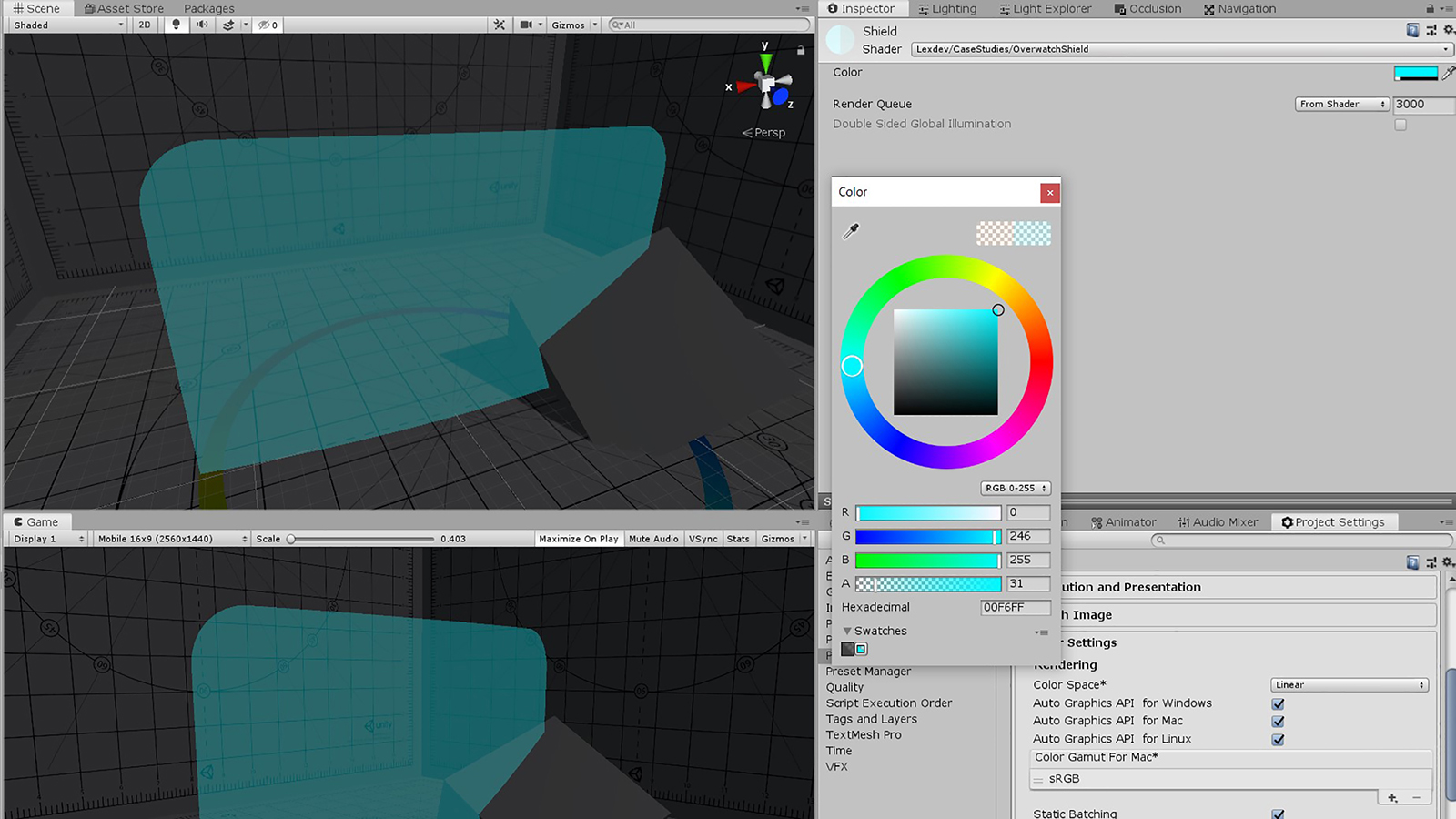
Since we changed stuff all over this place in this chapter and our code is still pretty short here’s the full shader file as it should look after this chapter:
Shader "Lexdev/CaseStudies/OverwatchShield"
{
    Properties
    {
        _Color("Color", COLOR) = (0,0,0,0)
    }
    SubShader
    {
        Tags {"RenderType" = "Transparent" "Queue" = "Transparent"}
        Cull Off
        Blend SrcAlpha One

        Pass
        {
            HLSLPROGRAM

            #pragma vertex vert
            #pragma fragment frag

            #include "UnityCG.cginc"

            struct appdata
            {
                float4 vertex : POSITION;
            };

            struct v2f
            {
                float4 vertex : SV_POSITION;
            };

            float4 _Color;

            v2f vert (appdata v)
            {
                v2f o;
                o.vertex = UnityObjectToClipPos(v.vertex);
                return o;
            }

            fixed4 frag (v2f i) : SV_Target
            {
                return _Color;
            }

            ENDHLSL
        }
    }
}The first effect we implement is the pulsating hex fields. In order to do that, we need one of the textures that are included in the template project. You can find them in “Assets/Textures”, for this section we use the HexPulse one.
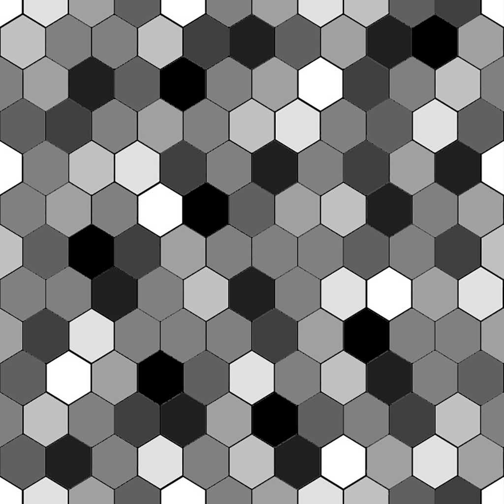
As you can see the texture resembles the final look of the effect. We have the hex fields in different greys, and the edges in black. In order to use the texture, the first thing we need are the vertices' UV coordinates. We can retrieve them from TEXCOORD0 in our appdata struct:
struct appdata
{
    float4 vertex : POSITION;
    float2 uv : TEXCOORD0;
};
UV coordinates are used to map the surface of a 3-dimensional mesh onto a 2-dimensional plane. If assigned, they are stored in the mesh's vertex data. A pair of UV coordinates (x and y) are the position of the vertex on the plane. Their values range from 0 to 1.
Since we need the UV coordinates in our fragment function to sample the texture there, we must pass it on to the v2f struct in our vertex function. Thus, a variable for it needs to be added to our v2f struct first. I am using the same register (TEXCOORD0) for this variable, since we don’t need the original UV value after the vertex function and we can simply override it.
struct v2f
{
    float4 vertex : SV_POSITION;
    float2 uv : TEXCOORD0;
};
In our vertex function, we can use the TRANSFORM_TEX function defined in UnityCG.cginc.
v2f vert (appdata v)
{
    ...
    o.uv = TRANSFORM_TEX(v.uv, _PulseTex);
    ...
}Using this function allows us to support Unity’s texture offset and tiling values. Each texture has some, but since there is only one set of UV coordinates we have to decide which ones we want to use. We’ll come back to this in the last chapter.
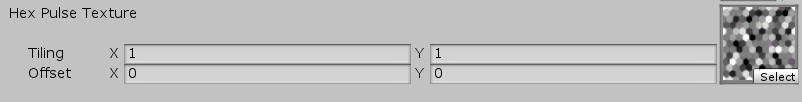
As you might have realized, we haven’t defined the _PulseTex variable we are using yet, let’s add it to our properties first.
Properties
{
    ...
    _PulseTex("Hex Pulse Texture", 2D) = "white" {}
}
The type for 2D textures we have to use in HLSL is sampler2D. In addition to the texture, we have to add a float4 with the same name, and suffix _ST.
sampler2D _PulseTex;
float4 _PulseTex_ST;
The _ST float4 variable is used to store the previously mentioned tiling and offset values (each for x and y) you can set in the inspector. Its name has to be correct for Unity to find the variable when using TRANSFORM_TEX. The tiling value in here will then be multiplied with the original UV coordinates, and the offset added to the result afterwards.
We can now sample the texture in our fragment function by using HLSL’s tex2D function. The result is a colour value; thus, we store it as fixed4. I am creating another fixed4 variable here called pulseTerm. For the moment we just multiply the textures grey value with our colour, we’ll add additional calculations here during the next steps.
fixed4 frag (v2f i) : SV_Target
{
    fixed4 pulseTex = tex2D(_PulseTex, i.uv);
    fixed4 pulseTerm = pulseTex * _Color;
    ...
}
All that’s left for us to do in order to display the texture is to add the pulseTerm to the rgb values of our result.
return fixed4(_Color.rgb + pulseTerm.rgb, _Color.a);The result should look like this:
We just created a fixed4 vector by providing a float3 (for rgb) and a single float value (for alpha) as parameters. Pretty awesome, right? HLSL allows us to do almost everything when it comes to parameters for a vector, we could have combined two float2’s for example. The same flexibility also exists when it comes to accessing only parts of a vector. While I used .rgb to get the first three parameters, .brg or .yxz would also be valid (even though it would lead to a different colour in this case).
I highly recommend that you look at this MSDN page to learn more about math operations in HLSL.
Let’s add a simple float variable to change the intensity of the pattern. To achieve that, we simply need to multiply it with our pulse term.
_PulseIntensity ("Hex Pulse Intensity", float) = 3.0float _PulseIntensity;fixed4 pulseTerm = pulseTex * _Color * _PulseIntensity;I chose 3.0f for the intensity, however you can adjust it to whatever you think looks good. With that, we are done with the basic pattern and can start animating it.
The basis for an animation like that is the sinus function. By multiplying our pulse term with the sinus value of the current time, we effectively multiply it with an ever-changing value from -1 to +1, creating a pulsating effect. Unity stores the current time inside _Time and we can access it anywhere within our code.
fixed4 pulseTerm = pulseTex * _Color * _PulseIntensity *
sin(_Time.y);The provided time variable in Unity is of type float4 and stores the time since level load. Depending on which value you are using it is scaled differently, _Time.y represents the unscaled time. Check out the documentation for more details.
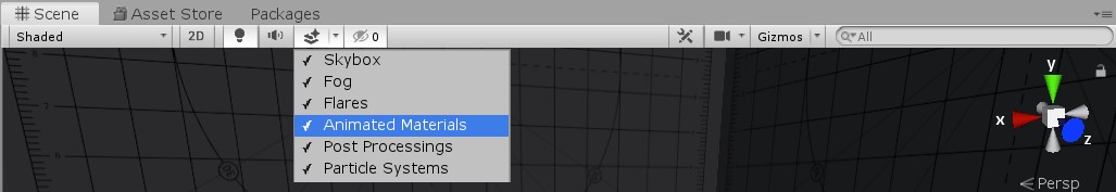
While shaders compile almost in real time, their animations are barely updating while in edit mode. This is due to Unity not updating the _Time variable regularly. You can force regular updates, for testing animations like these, by enabling “Animated Materials” in the effect button menu of the scene view.
The result after adding this to our shader looks weird. That’s due to us multiplying our colour with a negative value half the time. To fix this, we have two options: We can either use abs() to make sure all our values are positive, or use max(value,0.0f) to clamp all of our negative values to 0. Second leads to half of our sinus function’s values being 0, which might look off compared to the original.
fixed4 pulseTerm = pulseTex * _Color * _PulseIntensity *
    abs(sin(_Time.y));
The animation looks a bit too slow at the moment, so we should add another float variable to be able to modify the time scale. Adding this variable works similar to one we added for the intensity.
_PulseTimeScale("Hex Pulse Time Scale", float) = 2.0float _PulseTimeScale;fixed4 pulseTerm = pulseTex * _Color * _PulseIntensity *
abs(sin(_Time.y * _PulseTimeScale));I think setting the value to 2.0f looks good for now, but you can try changing it a bit and check out the result. A larger value leads to more of a flashing instead of the pulse we want to have, a slower value to an even slower pulse animation.
Our shield currently uses the same sinus value at every point on the surface. In order to achieve the final look of the shield we have to add positional information to our animation. In the first chapter’s analysis of the effect we saw that the pulse starts at the centre of the shield and moves along the local x-axis. The pulse’s value doesn’t change along the y-axis, e.g. for every local x-coordinate all y-coordinates have the same value.
When I built the model of shield, I made sure that the pivot point (origin) of the shield is at its centre, that makes it way easier for us to implement the next step. All we have to do is get the local (object) position of our vertices and pass them on to our fragment function where we can use it for our animation.
To access the vertices position, we have to add it to our appdata struct. You might have realized that it’s actually already in there, we use the vertex position in our vertex function where we transform it to clip space for the rasterizer. Since we need the vertex position in local (object) space we must add another variable to our v2f struct. All variables in there have to be assigned to a specific register (like SV_POSITION, TEXCOORD0, etc.). There isn’t a specific one for this, so let’s just use TEXCOORD1.
struct v2f
{
    ...
    float4 vertexObjPos : TEXCOORD1;
};While TEXCOORD0 is usually used to store the primary UV coordinates of the mesh, the TEXCOORD registers aren’t purpose bound and can be used for whatever you want. They are all capable of storing up to a float4. Check out the documentation for more details.
Obviously, we have to fill the variable with the desired value, so in our case we can simply pass on the original vertex pos in our vertex function.
v2f vert (appdata v)
{
    ...
    o.vertexObjPos = v.vertex;
    return o;
}
All that’s left is adding the x-coordinate to our scaled time and we should see a proper moving wave on our shield.
fixed4 pulseTerm = pulseTex * _Color * _PulseIntensity *
    abs(sin(_Time.y * _PulseTimeScale + i.vertexObjPos.x * 50.0f));
I multiplied the value with 50 to properly scale the x-coordinate and make the result look right. Let’s replace this value with another float variable to enable us to change the value from within Unity.
_PulsePosScale("Hex Pulse Position Scale", float) = 50.0float _PulsePosScale;fixed4 pulseTerm = pulseTex * _Color * _PulseIntensity *
abs(sin(_Time.y * _PulseTimeScale + i.vertexObjPos.x * _PulsePosScale));One advantage of using the local position for effects is that it is independent of the object’s orientation. If you enter the play mode you can see that the shield animation looks the same, no matter the current rotation of it.
The wave itself however doesn’t look quite right yet. At the moment it originates on one side of the shield and moves towards the other one, we want it to originate at the centre. It’s already moving correctly for negative local x-coordinates (one side of the shield basically moves from the centre towards the edge); we have to change the direction for positive ones. Since the shield was build symmetrically by me, we can use abs() to assure that all values are positive and then multiply them with -1, effectively flipping the sign of the positive values.
fixed4 pulseTerm = pulseTex * _Color * _PulseIntensity *
    abs(sin(_Time.y * _PulseTimeScale - abs(i.vertexObjPos.x) * _PulsePosScale));
We are going to need this value (which basically represents the horizontal distance from the centre) again later, so let’s store it in a variable
float horizontalDist = abs(i.vertexObjPos.x);fixed4 pulseTerm = pulseTex * _Color * _PulseIntensity *
abs(sin(_Time.y * _PulseTimeScale - horizontalDist * _PulsePosScale));Almost there! Just one part left for this effect: The hex tile-based offset of the animation. The idea is to additionally offset the parameter of the sinus function by the value in the hex texture we are using. You can think of it as us modifying the distance value we just created by the value of the hex field, which means that black fields will remain the same, white fields will be offset by 1. So basically, we are calculating the field’s sinus value for a position on the shield where it actually isn’t located. That means we get different sinus values for each field based on its colour.
We are already sampling the texture in our fragment function and store the result in the pulseTex variable, so we can simply use that one and add it to our pulse term.
fixed4 pulseTerm = pulseTex * _Color * _PulseIntensity *
abs(sin(_Time.y * _PulseTimeScale - horizontalDist * _PulsePosScale + pulseTex.r));The sinus function expects a float parameter, so we have to use a single value from our fixed4 colour. The alpha of this texture is always 1 so we can’t use that one here. That leaves us with r, g, and b. Since our texture is just different greys, r, g and b are the same and we can choose either one.
I picked r because it’s the first one, but the others work just as well.
Let’s add one more modifier variable to be able to adjust the impact the texture value has.
_PulseTexOffsetScale("Hex Pulse Texture Offset Scale", float) = 1.5float _PulseTexOffsetScale;fixed4 pulseTerm = pulseTex * _Color * _PulseIntensity *
abs(sin(_Time.y * _PulseTimeScale - horizontalDist * _PulsePosScale + pulseTex.r * _PulseTexOffsetScale));I set the modifier’s value to 1.5 for now, we’ll adjust all of the shader’s variables at the end after we’re done implementing all the effects.
Alright, we are done with the first component of our shield! Looks pretty good already, don’t you think? Next up, we’ll add the highlights for the edges of the hex fields.
As mentioned in the analysis of the shader, this effect looks as if it follows the edges around the hex field towards the corners of the shield. However, it is simply a diamond pattern with increasing size.
With that in mind it’s not as complicated to implement this part as it looks. To be honest, we’re basically doing what we did last chapter, therefore I’ll go through everything a little bit faster this time. To simplify things for us, I created a texture with just the edges.
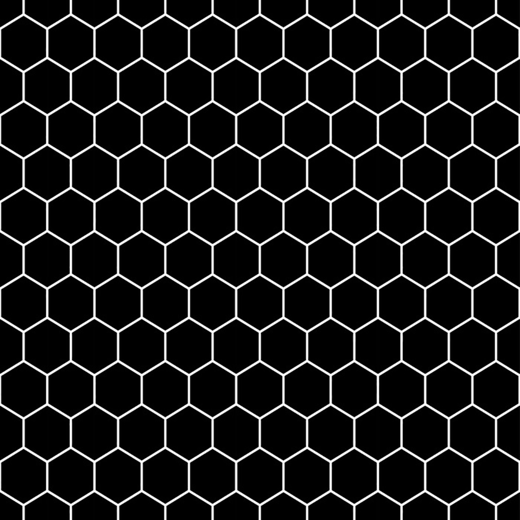
First, let’s add our new texture. We already have our UV coordinates in the fragment function, so all we must do is add a property, add the HLSL variables and sample it in our fragment function.
_HexEdgeTex("Hex Edge Texture", 2D) = "white" {}sampler2D _HexEdgeTex;
float4 _HexEdgeTex_ST;fixed4 hexEdgeTex = tex2D(_HexEdgeTex, i.uv);Next, create a term variable for the edge highlight, and multiply it with our colour. As with the field highlights, we can then add this term to the result. Let's add an intensity multiplier while we're at it.
_HexEdgeIntensity("Hex Edge Intensity", float) = 2.0float _HexEdgeIntensity;fixed4 hexEdgeTerm = hexEdgeTex * _Color * _HexEdgeIntensity;return fixed4(_Color.rgb + pulseTerm.rgb + hexEdgeTerm.rgb, _Color.a);For an intensity value of 2.0f, the result should look like this:
If you look at the original shield again, you’ll realize that the edge highlights are using more of a red colour instead of orange. To simplify things and to make the shader more adjustable, let’s add another colour variable and change it in the edge term.
_HexEdgeColor("Hex Edge Color", COLOR) = (0,0,0,0)float4 _HexEdgeColor;fixed4 hexEdgeTerm = hexEdgeTex * _HexEdgeColor * _HexEdgeIntensity;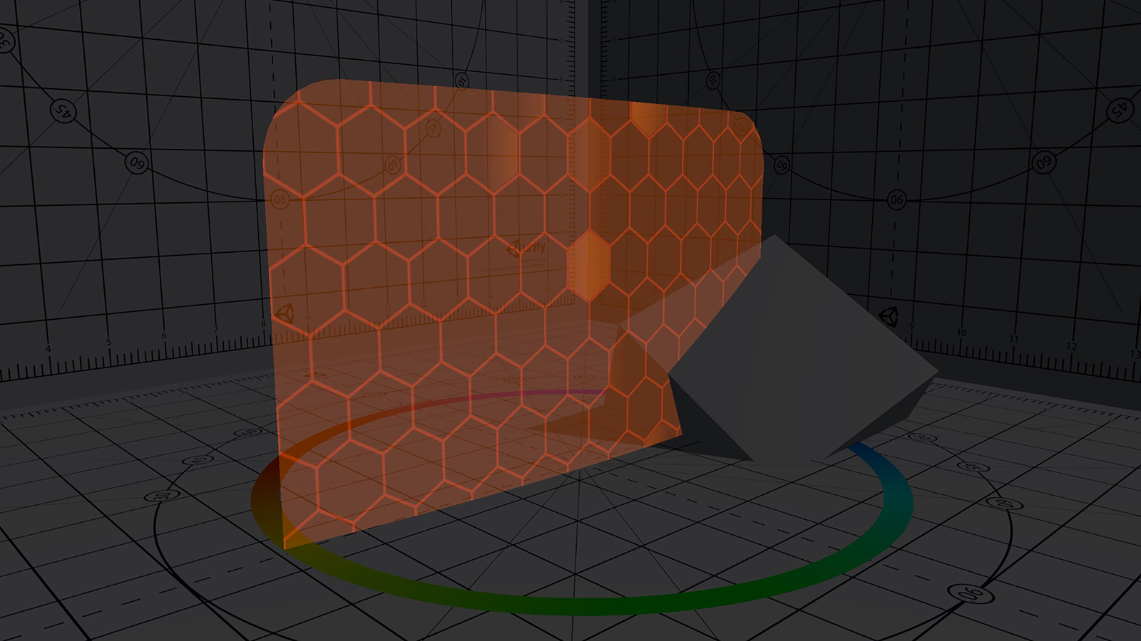
Much better. Now we only have to limit the effect to a specific area and animate it.
The basis is again the sinus of the time, this time inside a maximum function to prevent it from having a negative value.
fixed4 hexEdgeTerm = hexEdgeTex * _HexEdgeColor * _HexEdgeIntensity *
    max(sin(_Time.y), 0.0f);
Just as we did for the last effect, we should add a modifier variable for the time scale.
_HexEdgeTimeScale("Hex Edge Time Scale", float) = 2.0float _HexEdgeTimeScale;fixed4 hexEdgeTerm = hexEdgeTex * _HexEdgeColor * _HexEdgeIntensity *
max(sin(_Time.y * _HexEdgeTimeScale), 0.0f);We arrived at the point where this effect’s implementation starts to differ from the previous one.
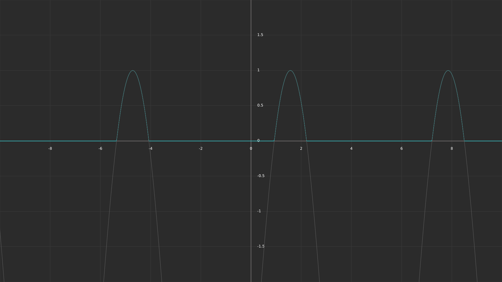
The first thing that’s different is the aspect ratio between pauses and pulses. At the moment the pauses take exactly as long as the pulses, due to us mapping half the sinus values to 0. The following plots should visualize it a bit better. The x-axis represents the time value, y the intensity of our effect.
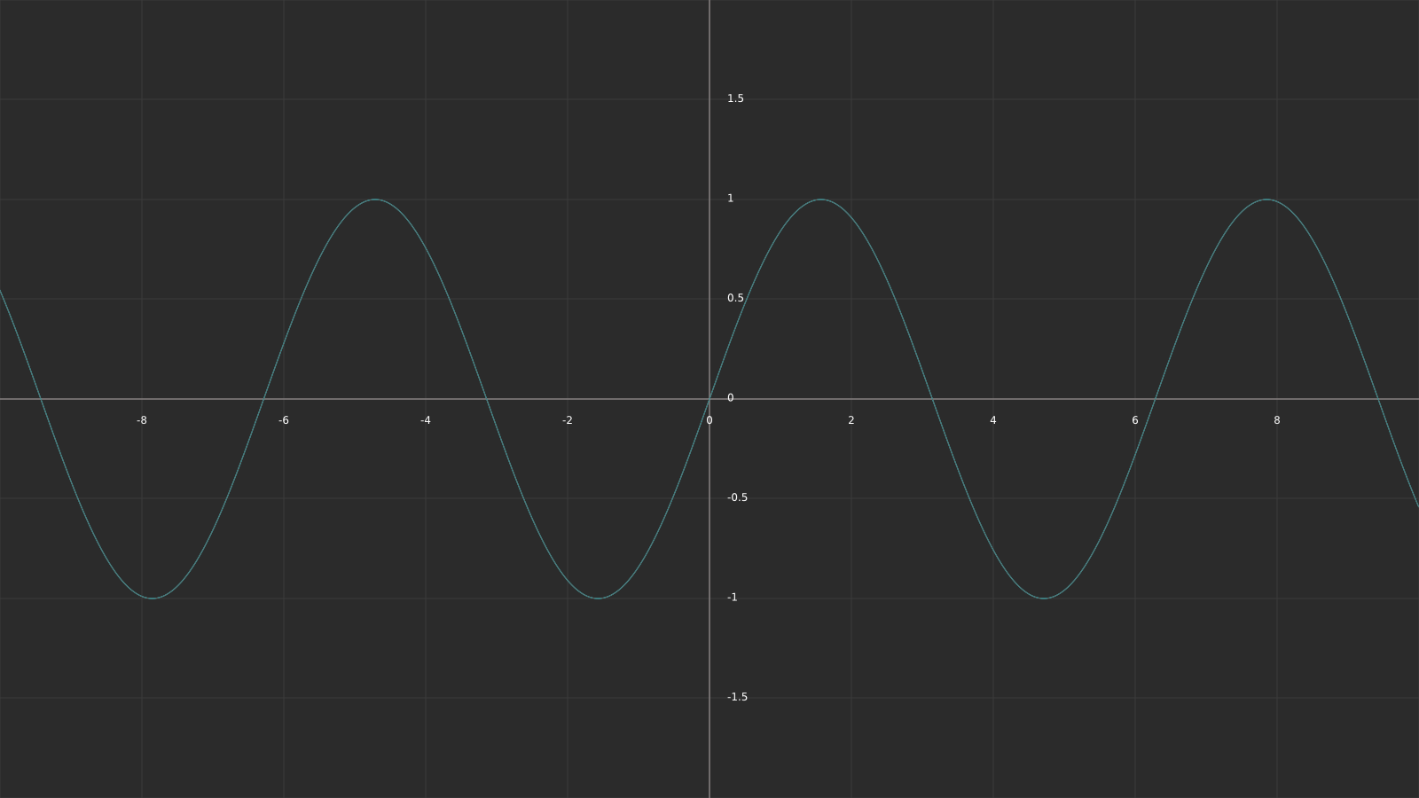
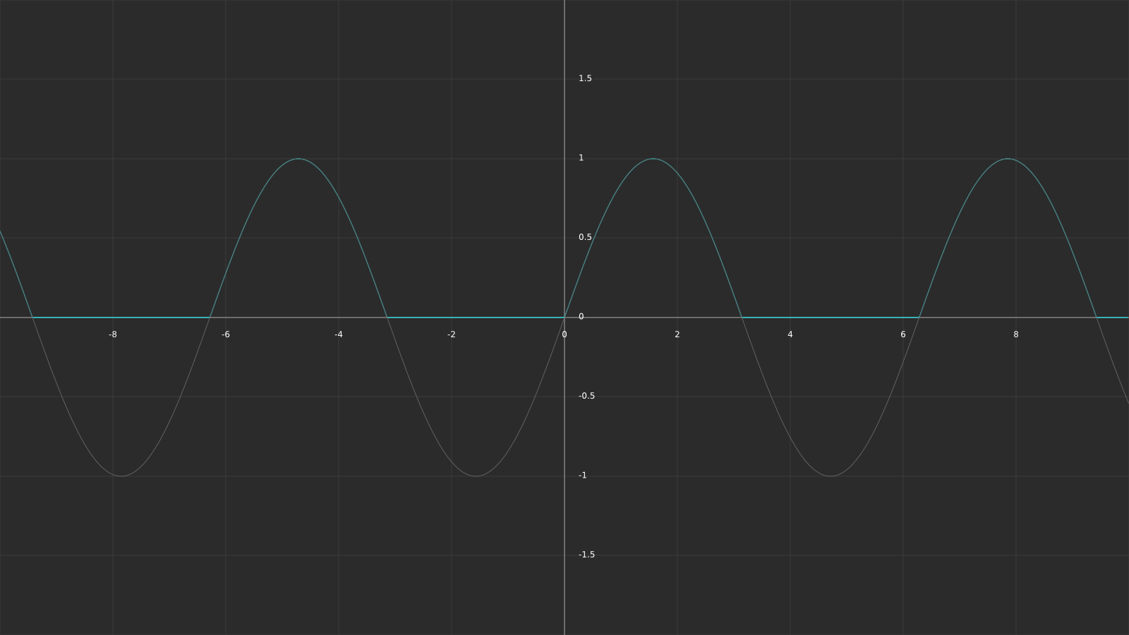
The first graph is our original sinus with just the time as input parameter, the second one is the sinus with the addition of the max function. To increase the pauses in between pulses, we can move the whole sinus down by a value between 0 and 1 (subtracting the value from the sinus function). For a value of 0.8, the result looks like this:
As you can see, the pauses in between pulses are now way longer compared to the length of the pulses. Let’s add this variable to our shader.
_HexEdgeWidthModifier("Hex Edge Width Modifier", Range(0,1)) = 0.8float _HexEdgeWidthModifier;fixed4 hexEdgeTerm = hexEdgeTex * _HexEdgeColor * _HexEdgeIntensity *
max(sin(_Time.y * _HexEdgeTimeScale) - _HexEdgeWidthModifier, 0.0f);Using Range(a,b) as type instead of floats adds the variable as slider to the Unity inspector, allowing us to limit the values the variable can have. Internally it is still a float variable.

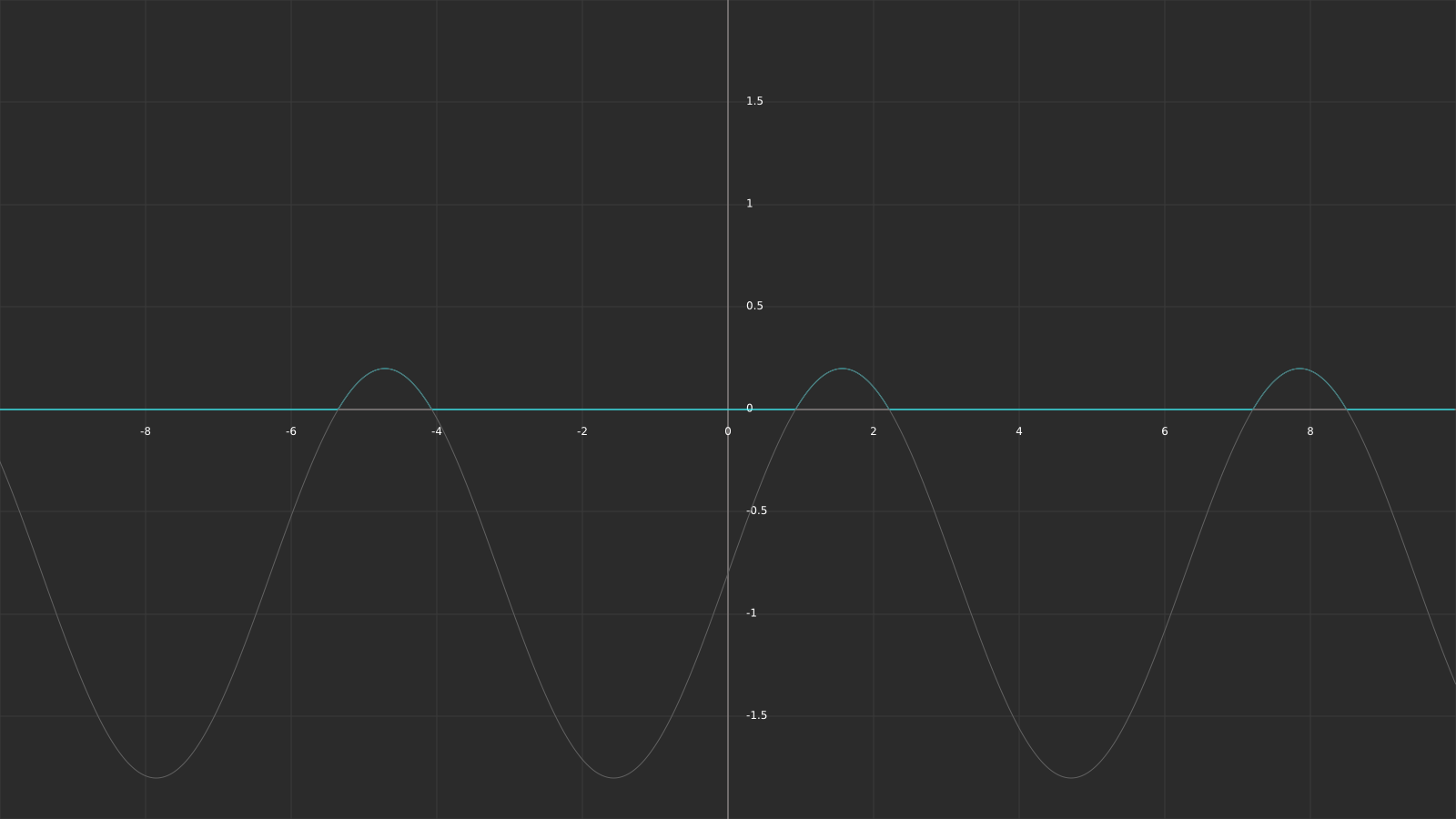
One issue that appears because of this implementation can clearly be seen in the graph; our resulting values don’t cover the range [0;1] anymore, but rather [0;1 - _EdgeWidthModifier]. Thus, we have to normalize the result, e.g. assure that the values of the function range from 0-1 again. This can be done by multiplying the function with 1 / (1 – _EdgeWidthModifier).
fixed4 hexEdgeTerm = hexEdgeTex * _HexEdgeColor * _HexEdgeIntensity *
max(sin(_Time.y * _HexEdgeTimeScale) - _HexEdgeWidthModifier, 0.0f) * (1 / (1 - _HexEdgeWidthModifier));In order to map the range [0;1 - _EdgeWidthModifier] to [0;1], we only have to look at what factor we have to multiply our _EdgeWidthModifier with to receive 1 (since 0 times whatever our term is still equals 0). So, what we have to do is solve (1 - _EdgeWidthModifier) * X = 1 for X. This can be done by dividing the term by (1 - _EdgeWidthModifier), resulting in our normalization function.
This leaves us with the following result:
Our effect now only blinks for a short moment, then pauses for a much longer time. All that’s left (again) is to add the spatial information. Instead of just moving the sinus wave along the x-axis we need to create a diamond pattern this time. The following graph should help you understand how you can calculate the values for this.
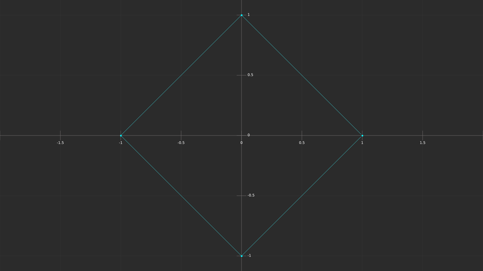
Since we have multiple y values per x value, this pattern can’t be described by a function, however it can be described by the following relation:
abs(y) + abs(x) = 1
Depending on the right side of the equation the size of the diamond is larger or smaller. That means that if we calculate the sinus of abs(x)+abs(y), we create a repeating diamond pattern with increasing radius. In combination with the time value the pattern moves.
We are already passing the local vertex position to our fragment function, and we are already calculating the horizontal distance. A variable for the vertical distance can simply be added here.
float verticalDist = abs(i.vertexObjPos.z);Based on the Unity coordinate system one might think that the y-axis of the object is up, however if you take a closer look at the shield you might realize that it’s rotated by -90 degrees around the x-axis. If you change this rotation to 0, or if you set the coordinate system of unity to local, you’ll see that the z axis is what we need.
Let’s add the distances to our sinus function as described above.
fixed4 hexEdgeTerm = hexEdgeTex * _HexEdgeColor * _HexEdgeIntensity *
    max(sin((horizontalDist + verticalDist) - _Time.y * _HexEdgeTimeScale) - _HexEdgeWidthModifier, 0.0f) *
    (1 / (1 - _HexEdgeWidthModifier));
Doesn’t look too bad, we should just add one more modifier for the diamond pattern to be able to adjust the physical distance between waves.
_HexEdgePosScale("Hex Edge Position Scale", float) = 80.0float _HexEdgePosScale;fixed4 hexEdgeTerm = hexEdgeTex * _HexEdgeColor * _HexEdgeIntensity *
max(sin((horizontalDist + verticalDist) * _HexEdgePosScale - _Time.y * _HexEdgeTimeScale) - _HexEdgeWidthModifier, 0.0f) *
(1 / (1 - _HexEdgeWidthModifier));I choose 80.0f for now, which should look like the following video. As with all the other variables, we’ll adjust the values once we’re done coding.
Another effect done! Only two things left to achieve the basic look: The glowing edge of the shield, and the intersection highlight. The edge highlight is simple, so the next chapter is probably the shortest one in this tutorial.
The bright gradient along the outer edge of the shield is mostly done by texture, we only need a couple of variables to be able to adjust the effect. The texture we are using is called HexBorder, and it looks like this (the dark background is not part of the texture, it’s transparent):

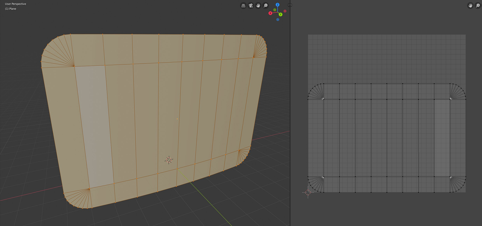
The UV coordinates and the texture align as you would expect, here’s an image of the UV mapping in blender:
In Unity, the unmodified texture on the model would look like this:
Let’s add the texture to our shader and multiply it with our basic colour value.
_EdgeTex("Edge Texture", 2D) = "white" {}sampler2D _EdgeTex;
float4 _EdgeTex_ST;fixed4 edgeTex = tex2D(_EdgeTex, i.uv);
fixed4 edgeTerm = edgeTex.a * _Color;return fixed4(_Color.rgb + pulseTerm.rgb + hexEdgeTerm.rgb + edgeTerm, _Color.a);The result should look like this:
Not quite perfect yet, we need to be able to adjust two values: The intensity and the thickness. For the intensity we can simply add a variable as we have done in the previous chapters for the other effects.
_EdgeIntensity("Edge Intensity", float) = 10.0float _EdgeIntensity;fixed4 edgeTerm = edgeTex.a * _Color * _EdgeIntensity;In order to change the thickness, we can look at how we can adjust the gradient of the texture. At the moment the gradient is linear, we can use pow() to make it exponential.
_EdgeExponent("Edge Falloff Exponent", float) = 6.0float _EdgeExponent;fixed4 edgeTerm = pow(edgeTex.a, _EdgeExponent) * _Color * _EdgeIntensity;Since our texture value is in the range [0,1], a higher exponent means that value falls faster if the exponent is higher. It think 6.0 looks about right for now. The result should look like this:
That’s it for this chapter! The next one won’t be as short, but it is the last effect we have to implement.
Even though the edge texture we added in the last chapter and the intersection highlight in this one are two separate effects, they must look as if they are the same continuous border at the edge of the shield. You’ll see some similarities between the two this chapter. What we are basically about to implement is a comparable effect, but instead of using a texture value in the effect’s term we calculate one based on the depth information.
In order to work with the depth texture, we need a C# script in which we set the camera’s depthTextureMode to DepthTextureMode.DepthNormals. I already prepared one, you can find it on the camera object in the scene. If everything works correctly, there should be a little info box in the camera component telling you that the camera renders the depth into a texture.

We can then access the depth texture like any other texture in our shader. The name has to be _CameraDepthNormalsTexture in order for Unity to find it.
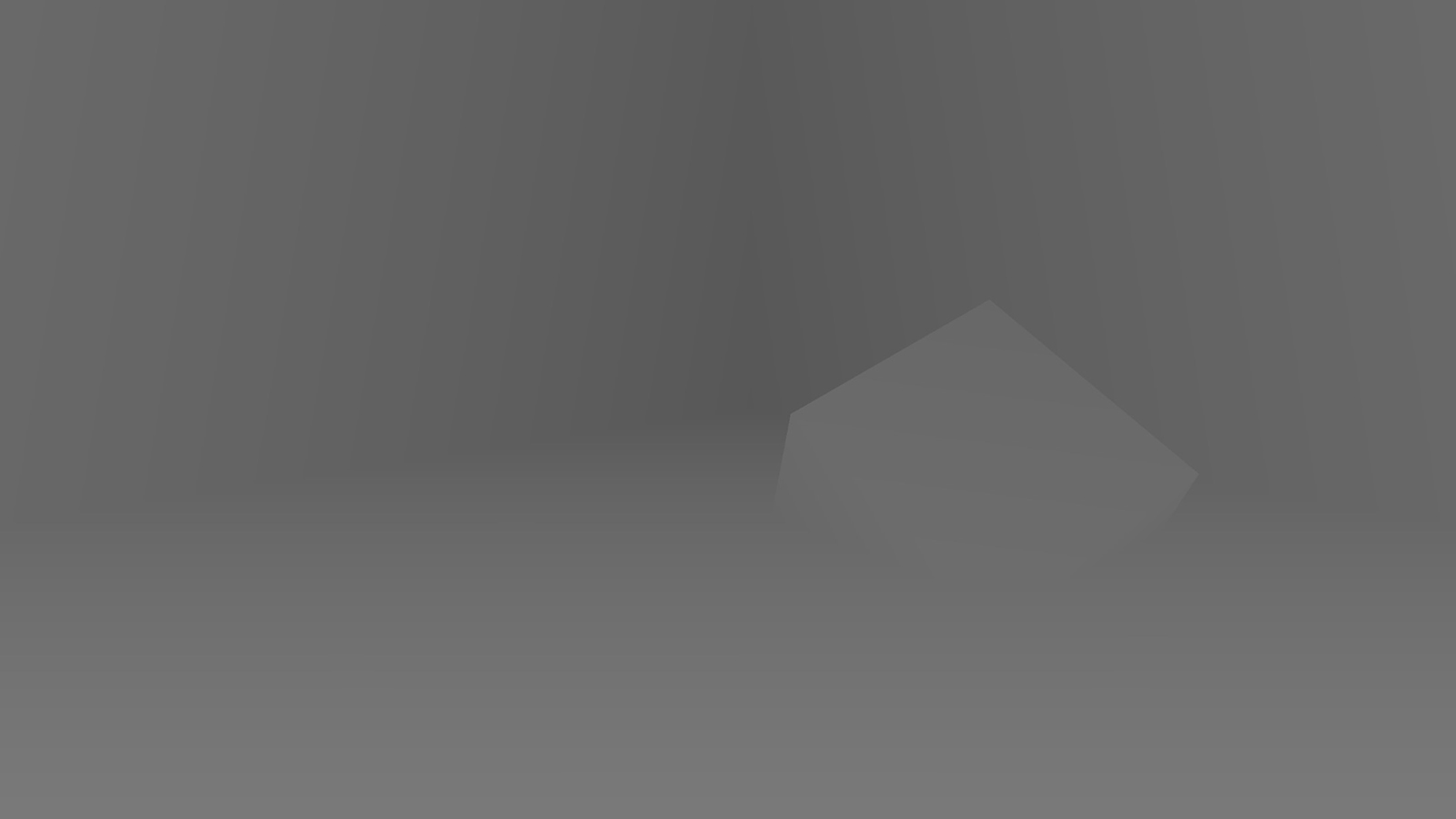
sampler2D _CameraDepthNormalsTexture;With that out of the way, let’s talk about the basic theory behind this effect. The idea is to calculate the depth of the shield for the respective pixel and subtract the depth value stored in the depth texture. If the distance between those is small, the distance between the shield and the background at that position is small, e.g. there is usually an intersection between shield and background nearby (the depth difference at the intersection Is zero). I rendered the depth texture for our current scene to help you understand how it looks.
While the basic idea behind this effect is simple, there are some pitfalls along the way we have to address, mostly due to camera parameters. Let’s start with the adjustments we need to do to the vertex function. We have to calculate the vertex's depth value (to compare it to the depth texture’s value later) and we need the screen position (not clip position) to sample the depth texture. To store both, add two new variables to our v2f struct for them.
struct v2f
{
    float4 vertex : SV_POSITION;
    float2 uv : TEXCOORD0;
    float4 vertexObjPos : TEXCOORD1;
    float2 screenPos : TEXCOORD2;
    float depth : TEXCOORD3;
};
To calculate the screen position, we can use one of the helper functions in UnityCG.cginc. It allows us to convert our clip position to the screen position.
o.screenPos = ComputeScreenPos(o.vertex);inline float4 ComputeScreenPos (float4 pos)
{
float4 o = pos * 0.5f;
o.xy = float2(o.x, o.y*_ProjectionParams.x) + o.w;
o.zw = pos.zw;
return o;
}Converting clip position to screen position is straight forward. We only have to multiply x and y by 0.5 and add the clip position's w component. _ProjectionParams.x is 1.0 or -1.0, depending on the render backend the y-coordinate starts at the bottom or top of the screen and needs to be flipped.
To calculate the depth, we have to calculate the vertex position in camera space first. In it, the z coordinate is the depth of the vertex. Since we want our depth values both to be positive for the comparison later in the fragment function, we multiply the depth by -1. At the moment, our depth value is the actual distance from the near plane to the vertex. The depth texture however stores values in the range [0;1], with 0 being at the near plane, 1 at the far plane. In order to be able to accurately compare the two depths, we have to divide the vertices’ depth value by the far plane distance. The far plane distance is stored in the _ProjectionParams w component.
o.depth = -mul(UNITY_MATRIX_MV, v.vertex).z * _ProjectionParams.w;Basically, all rendering parameters are stored in variables provided by Unity. You can find all of them in the documentation.
With that done, we can move on to the fragment function. First, we have to calculate the distance between the depth texture and the depth value we calculated in the vertex function. In theory, that’s as easy as doing this:
float diff = tex2D(_CameraDepthNormalsTexture, i.screenPos.xy).r - i.depth;However, we have some issues here that need to be fixed. First, we have to divide our screen position coordinates by their w component. This is sometimes called the perspective divide, basically we adjust our screen position for the skewing of the coordinates due to the perspective camera. The second thing we need to change is the channels of the DepthNormals texture we read our data from. As the name suggests, the texture also stores normal information, therefore we must access the right channels to get the depth data. Even though the depth value can be stored in one float variable, it is encoded into two channels (z and w) of the texture to improve the precision. To decode the value, we can use the DecodeFloatRG function in UnityCG.cginc.
float diff = DecodeFloatRG(tex2D(_CameraDepthNormalsTexture, i.screenPos.xy / i.screenPos.w).zw) - i.depth;If you want to learn more about this, checkout this great article on learnopengles.com.
For a full list of helper functions in UnityCG.cginc, check out the documentation.
At this point we have the difference between the shield’s depth and the environment in the range [0;1], with 0 being at the near plane, 1 at the far plane. A further away far plane would therefore lead to a larger highlight, not ideal. We can simply fix this by dividing the difference by the far plane distance. This gives us the distance between shield and environment in actual units, independent of the camera and its settings. Remember, we want to use this difference instead of the texture value in the previous effect, it should therefore have the range [0;1].
If you take another look at the image of the unmodified texture on the shield, you can see that the border is about 1 unit thick, that helps us with the mapping of the depth difference to the appropriate range. We can simply use a min function to clip all values that are too large to 1. This gives us the proper gradient, we just have to invert it (a small depth difference should lead to a higher intensity).
float intersectGradient = 1 - min(diff / _ProjectionParams.w, 1.0f);The rest of this effect works just as the previous one.
_IntersectIntensity("Intersection Intensity", float) = 10.0
_IntersectExponent("Intersection Falloff Exponent", float) = 6.0
float _IntersectIntensity;
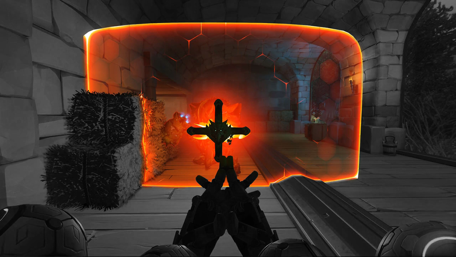
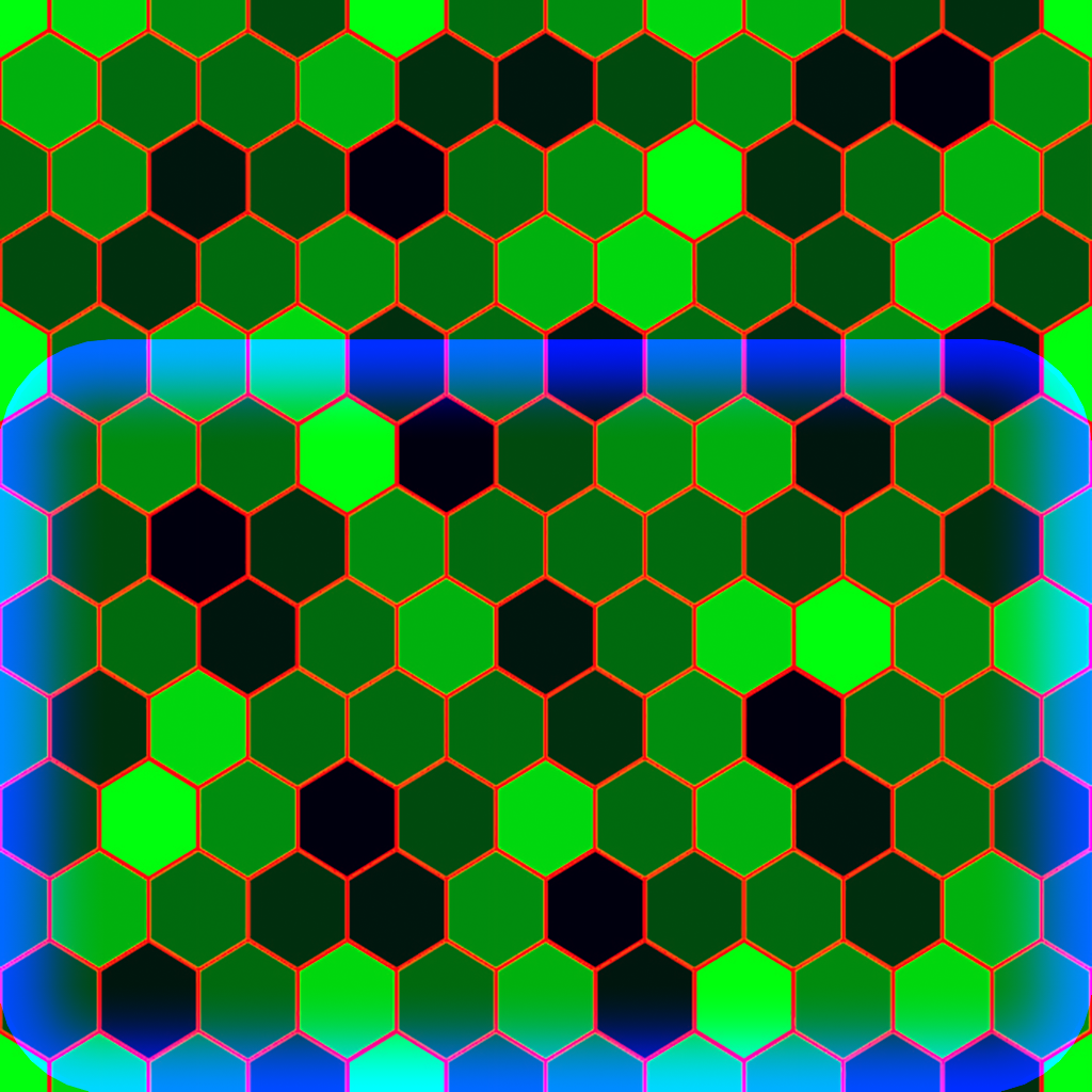
float _IntersectExponent;fixed4 intersectTerm = _Color * pow(intersectGradient, _IntersectExponent) * _IntersectIntensity;return fixed4(_Color.rgb + pulseTerm.rgb + hexEdgeTerm.rgb + edgeTerm + intersectTerm, _Color.a);With that, we are done implementing all the effects! Depending on the values you choose for the intensity of the border and the intersection highlight the two should look identical and blend perfectly into each other. We are going to adjust the values of the variables and add some post processing in the next chapter, for now the result should look like this:
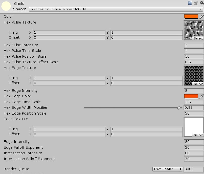
Now that we have all our variables in there, you should take some time and adjust them, so the shield looks the way you want. The values I am using in the final version of the project are:
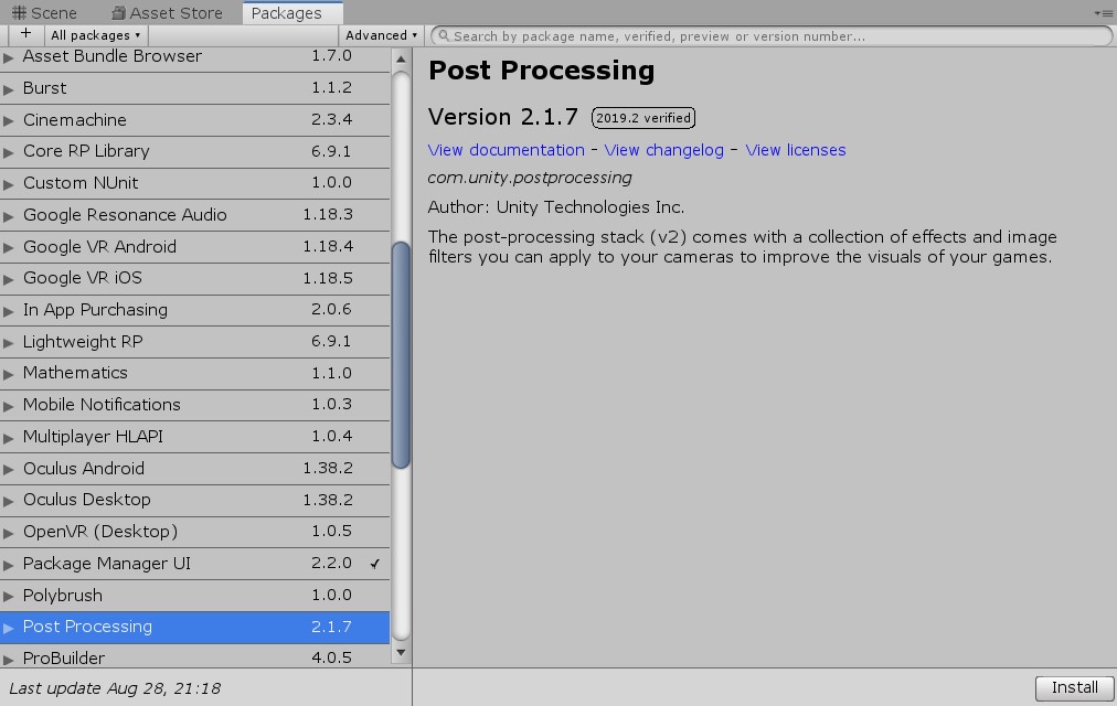
Let’s add some post processing to improve the result even more. First, we have to add the post processing package to the project. Go to Window->Package Manager to open the package list. Search for Post Processing and click install.
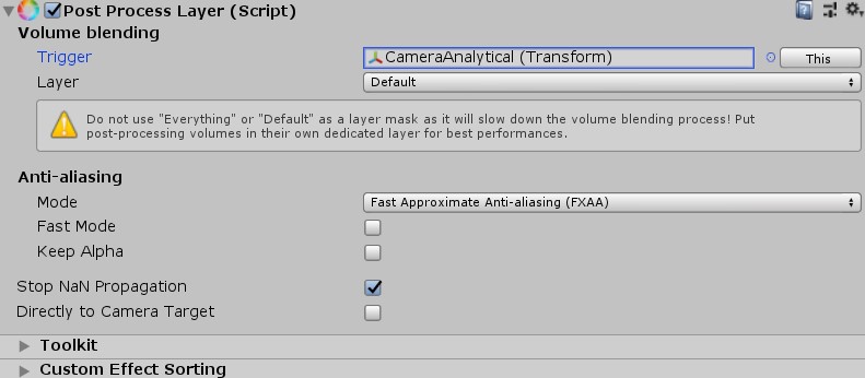
Once that’s done, add a Post Process Layer component to the main camera and choose an anti-aliasing mode. For this project FXAA should do just fine. You also have to set the Layer to default in order for the post processing to work. As Unity tells you it is not ideal to use default, however it’s totally fine for testing purposes like here.
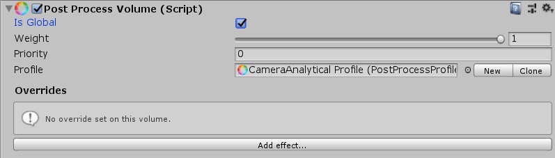
The second component we need to add to the camera is a Post Process Volume. Mark Is Global true and click the new button to create a new empty post processing profile.
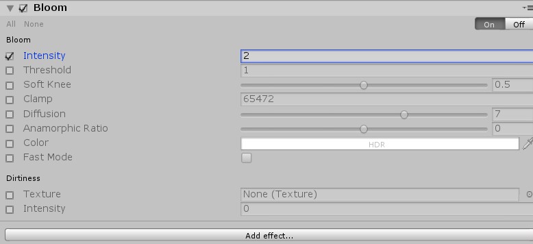
As with the material settings, you should take some time and experiment with the different settings and options. The most important one is bloom, which should be added to give the shield more of a glowing effect.
While this tutorial’s focus isn’t about optimisation, I wanted to tell you about one major improvement we can do to our shader. At the moment we have 3 different greyscale textures which means that each textures r,g and b channels have the same value. We could therefore store all the information of one texture in just one channel and use the other channels for something else. In the case of the shield, we could for example store the HexEdge Texture in the red channel, the HexPulse texture in the green channel and the HexBorder texture in the blue one. I prepared this texture for you, you can find it in the Textures folder.
Using this texture instead of the three individual ones has 4 advantages:
1. We save a lot of disk space in our project.
2. During runtime, we only have to store one instead of three textures in memory, which reduces the amount of it we need and improves load times.
3. In our shader, we only need to sample one texture (using tex2D). Texture sampling can be a costly operation.
4. When we use TRANSFORM_TEX in our vertex function, it currently only uses the offset and tiling of our first texture, the values of the other two are being ignored. If we only have one texture, we don’t run into this problem.
Changing the implementation is easy, let’s start by adding the texture property and variables.
_MainTex("Hex Texture", 2D) = "white" {}sampler2D _MainTex;
float4 _MainTex_ST;We have to change the TRANSFORM_TEX parameters in our vertex function as well.
o.uv = TRANSFORM_TEX(v.uv, _MainTex);Now, we can remove all the old textures and their variables. We don’t need them anymore and can therefore delete all the following lines.
_PulseTex("Hex Pulse Texture", 2D) = "white" {}_HexEdgeTex("Hex Edge Texture", 2D) = "white" {}_EdgeTex("Edge Texture", 2D) = "white" {}sampler2D _PulseTex;
float4 _PulseTex_ST;sampler2D _HexEdgeTex;
float4 _HexEdgeTex_ST;sampler2D _EdgeTex;
float4 _EdgeTex_ST;The only thing that’s left is to sample the new texture once in the fragment function and to replace the old tex2D calls.
fixed4 tex = tex2D(_MainTex, i.uv);fixed4 pulseTex = tex.g;fixed4 hexEdgeTex = tex.r;fixed4 edgeTex = tex.b;The result should look exactly the same as before, however the shader is way more optimised now.
This tutorial got way longer than I anticipated, but I think if you worked through all of this the result is definitely worth it. In case you had any issues along the way, check out the final version of the project.
Final ProjectYou can contact me on twitter if you have additional questions, want to leave some feedback or even suggest topics for future tutorials there. If you adapt the shader and build something new based on it, I would love to see it so make sure to share that!
Get the tutorial project from GitHub - It contains all the assets necessary to achieve the final result!
Help me to create more amazing tutorials like this one by supporting me on Patreon!
Make sure to follow me on Twitter to be notified whenever a new tutorial is available.
If you have questions, want to leave some feedback or just want to chat, head over to the discord server! See you there!
Projects on this page are licensed under the MIT license. Check the included license files for details.

If you like the tutorials and want to support me, head over to Patreon to do so! You'll also get access to some amazing perks like special discord roles with priority support!
I'd like to get in touch and read what you think about the site.
Feedback is always appreciated!
Feel free to send me suggestions for future tutorials.
Questions and messages from patrons will be answered with a higher priority!